Vacuum valve and compression storage bags including the valve

a vacuum valve and compression storage bag technology, applied in the field of vacuum valves, can solve the problems of increasing the cost of bag manufacture and the corresponding cost to the consumer, bulky valves, and non-flexible, and achieve the effects of less packaging, less shelf space for display, and simple and inexpensive manufacturing

Active Publication Date: 2016-03-29
SC JOHNSON & SON INC
View PDF45 Cites 3 Cited by
  • Summary
  • Abstract
  • Description
  • Claims
  • Application Information

AI Technical Summary

Benefits of technology

[0004]The present invention is directed to valves suitable for use in vacuum compression storage bags for clothing and other items, and the combination of the valves with such storage bags, wherein the valves are simple and inexpensive to manufacture. The valves are compact and flexible including a stand-off to allow for evacuation of air from a storage bag to which it is attached after the bag has been closed with the item(s) to be stored therein. The bags can be made as a flat bag having a first side wall, a second side wall and a bottom portion which form a two walled bag and has an open top portion for receiving and removing items to be stored, such as clothing, blankets or other items. The bag further includes a closure mechanism near the open top of the bag, such as a zipper closure, which provides for a re-closable bag. The bag can also have a 3-dimensional shape including a bottom wall, four side walls and a top wall to provide a rectangular or square “block” configuration. The top wall may be attached on one side to a side wall with a closure mechanism, such as a zipper, to attach the other three edges of the top wall to the other side walls. The bag includes a one-way valve for evacuation of air from the bag after the material to be stored has been placed in the bag and the closure mechanism closed. The air is evacuated using a pump or vacuum hose (attached to a suitable source of vacuum) placed over the valve. The present invention provides for an improved valve with stand-off which is compact and flexible, allows for air flow and evacuation of air from the bag, and requires less packaging which, accordingly, requires less shelf space for display in a store or storage in a user's home.
[0005]The improved valve with stand-off of the present invention is made from a plastic material such as polyethylene, polypropylene or other thermoplastic material. The valve includes a check valve (e.g. a label-type check valve) with an opening therethrough and an adhesive on an underside surface thereof, a center carrier film with an opening therethrough, and a plastic stand-off having a plurality of protrusions, preferably in the form of ribs, projecting from an underside thereof and including an opening therethrough. The plastic stand-off has a degree of rigidity greater than the check valve or carrier film which is provided by being constructed by extrusion, embossing, cast forming or the like. The degree of rigidity provided to the plastic stand-off can be provided based on various combinations of the stand-off's physical structure, plastic material from which it is made and process of formation, and is such that the rigidity prevents collapse or deformation of the stand-off and, thus the valve, under the force of vacuum pressure applied to the valve. The center carrier film is coated on an exterior surface thereof with an adhesive, wherein at least a portion of the adhesive is on an underside surface of the carrier film. The plastic stand-off is cut from a plastic tape or strip to form the stand-off.
[0006]The valve is provided by affixing the underside of the check valve to the topside surface of the carrier film, and affixing the topside surface of the plastic stand-off to the underside surface of the carrier film. The openings in the check valve, carrier film and stand-off are all aligned in the constructed valve and in use are also aligned with an opening in a wall of a compression storage bag. The carrier film is sized, and the adhesive on the exterior surface of the carrier film extends thereon, so that the carrier film will affix over the hole in the storage bag and extend onto an adjacent wall portion of the bag surrounding the hole where the adhesive serves to affix the valve to the wall of the bag and thereby hold the valve in place with respect to the bag. Adhesive on the exterior surface of the carrier film, thus serves the function of affixing the plastic stand-off with protrusions to the carrier film in formation of the valve, as well as hold the valve in place with respect to the storage bag. By this structure, the stand-off with projecting protrusions extends in use through the hole in the wall of the compression bag and into the interior space of the bag.
[0007]The valve may be formed by a variety of geometries, i.e., circular, rectangular, square, triangular, etc., with circular being preferred. The stand-off must be of sufficient length and width to have the stand-off protrusions extend inwardly through the hole in the bag wall into the interior storage portion of the bag so that when a pump or vacuum hose is placed over the valve to evacuate air, the protrusions of the standoff will maintain space between the bag wall to which the valve is adhered and the contents of the bag to thereby provide for air flow and evacuation of air from the bag through the aligned holes of the bag and valve.
[0008]An advantage of the plastic stand-off with protrusions being provided by extrusion, embossing, cast forming and the like is that it has sufficient rigidity to allow for air flow and not collapsing or deforming while also based on its compact size not interfering with the flexibility of the overall valve structure. The combined valve structure allows the valve to be smaller, in terms of area (width×length) and depth (thickness), so as not to interfere with packaging of the bag for display and storage purposes thereby allowing for more compact packaging as compared to currently marketed storage bags. The rigidity of the plastic stand-off due to being extruded, embossed, cast formed or the like provides strength to maintain an air passageway up to and through the opening passageway in the valve to accomplish the desired air evacuation of the storage bag and, thereby, compression of the bag.

Problems solved by technology

Such valves are bulky and non-flexible, as well as increase the cost of manufacture of the bag and the corresponding cost to the consumer.

Method used


Image

  • Vacuum valve and compression storage bags including the valve
  • Vacuum valve and compression storage bags including the valve
  • Vacuum valve and compression storage bags including the valve

Examples


Embodiment Construction

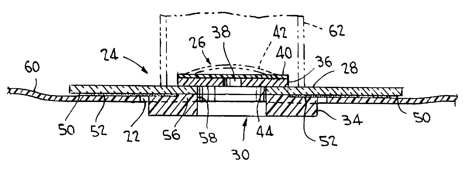
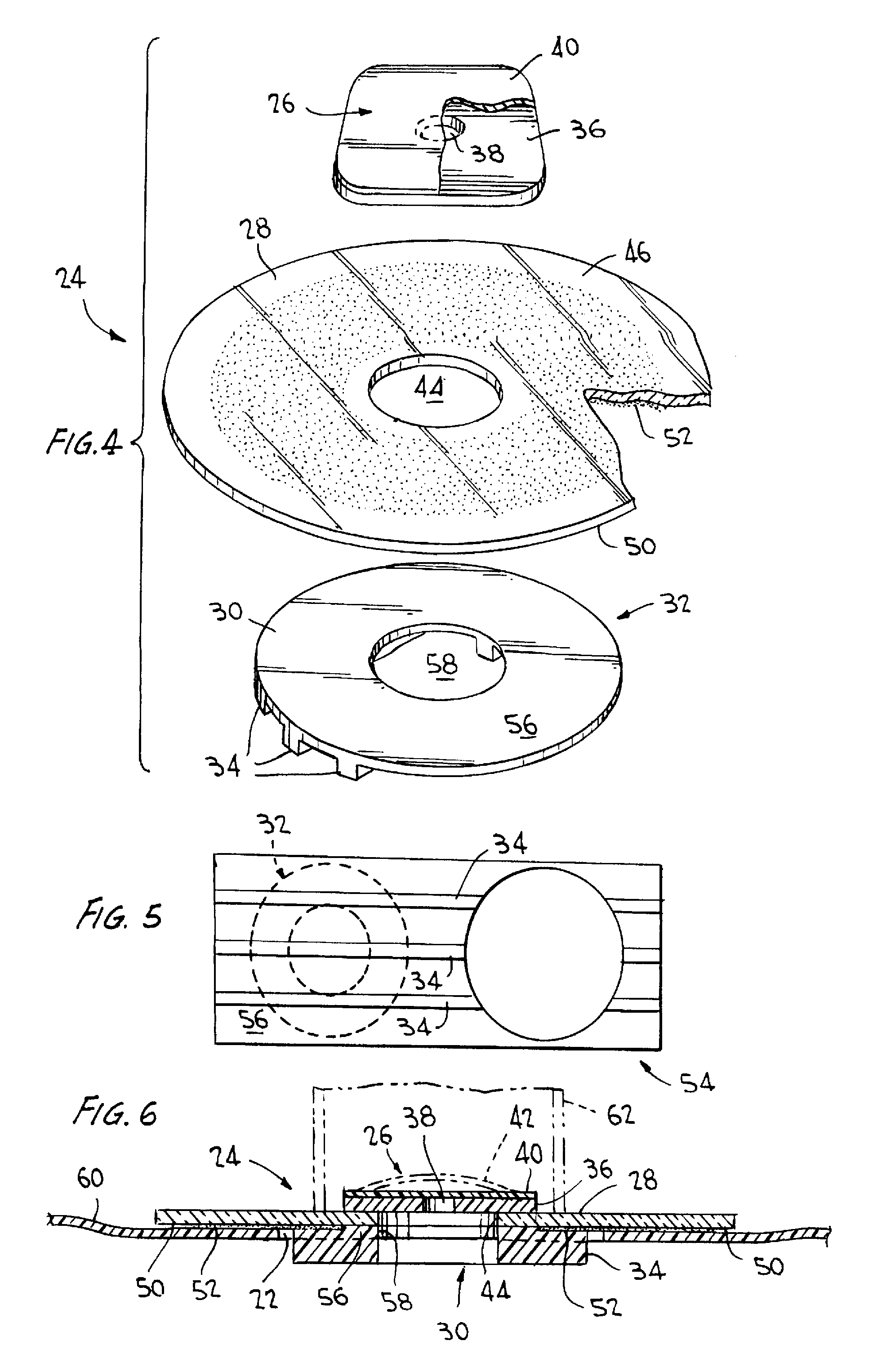
[0016]The present invention is directed to valves and the valves in combination with vacuum compression storage bags. The valves are simple and inexpensive to manufacture and are advantageously flexible and compact in structure while providing for good air flow during evacuation of air from a vacuum compression storage bag to which it is affixed in use. The valve includes a stand-off, including projecting protrusions (for example, ribs), which provides for efficient evacuation of air from a vacuum compression storage bag after the bag is filled with items, e.g. clothing, blankets and other material, to be stored and closed.

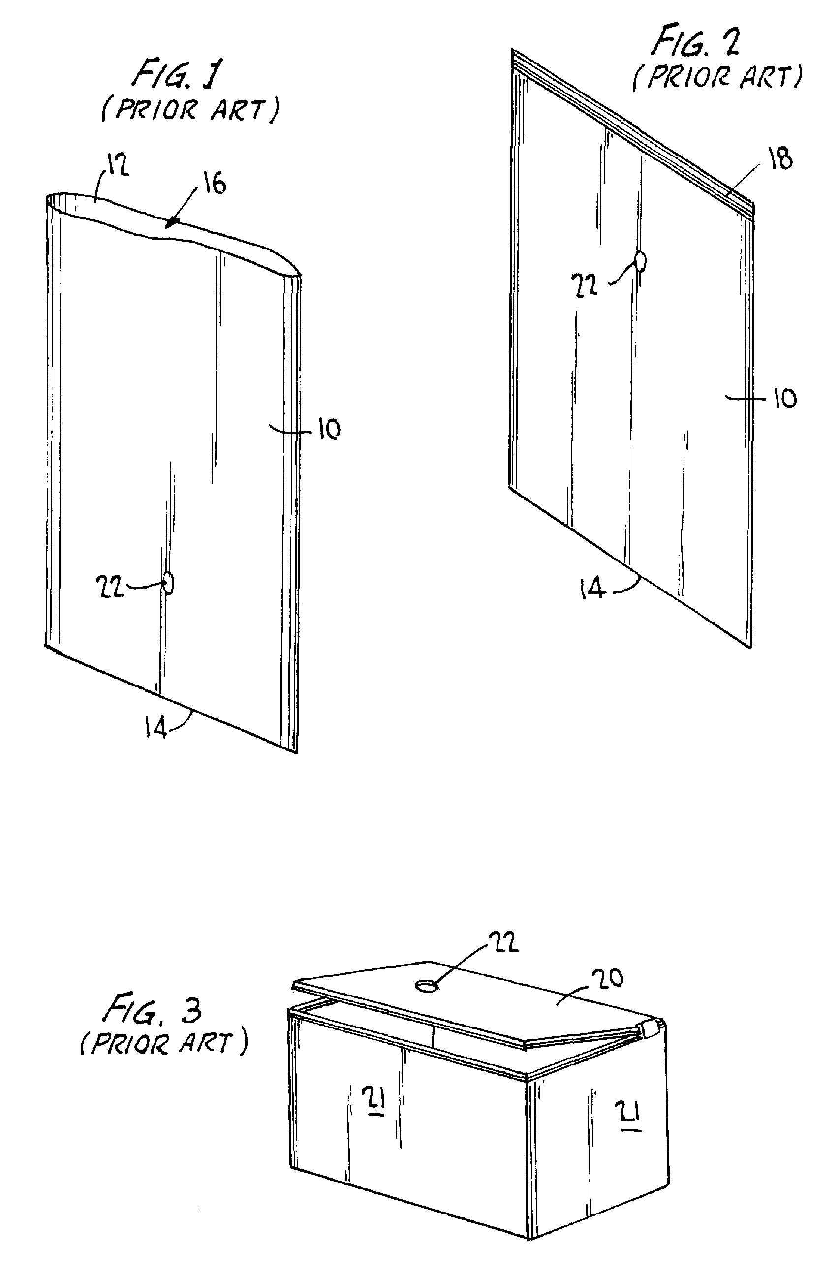
[0017]Referring generally to FIGS. 1-3, flat vacuum compression storage bags, e.g. in a range of about 18 inches by about 20 inches to about 35 inches to about 48 inches, include a first side wall 10, a second side wall 12 and a bottom portion 14 which forms the bag and having an open top portion 16 for receiving and removing items to be stored, such as clothing, ...


PUM


Abstract

Valves useful in vacuum compression storage bags are described. The valve includes a check valve, a carrier film having adhesive on a surface thereof, and a plastic stand-off with projecting protrusions. The check valve, carrier film and stand-off each have an opening therethrough which when affixed together align to provide a passageway through the valve. When used with a vacuum compression storage bag, the valve is aligned with a hole through a wall of the bag to provide an air flow passageway through the aligned holes from the interior of the bag through the valve when vacuum force is applied over the valve and the bag sealed. The stand-off extends inside the bag to prevent contents therein from blocking air flow from inside the bag through the valve during vacuum evacuation of air from the bag. The stand-off has a rigidity to prevent collapse of the valve under vacuum force.

Description

FIELD OF INVENTION[0001]The present invention relates to valves for and in combination with vacuum compression storage bags. More specifically, the invention is directed to a flexible compact valve for affixing to a vacuum compression storage bag for clothing and other items, wherein the valve includes a stand-off for optimizing the air flow and evacuation of air from the bag.BACKGROUND OF THE INVENTION[0002]Vacuum compression storage bags are known in the art. For example, SPACE BAG® brand vacuum compression storage bags are commercially available for storage of clothing and other items. Such storage bags can be flat bags including a first side wall panel and a second side wall panel which side wall panels are sealed at the side edges and the bottom edge of each other forming a bag having an open top as shown in FIG. 1. These bags further include a re-closable closure mechanism near the top portion of the bag for opening and closing the bag as illustrated in FIG. 2. Compression sto...

Claims


Application Information

Patent Timeline
Patent Type & Authority Patents(United States)
IPC IPC(8): B65D33/01B65D81/20F16K7/17
CPCB65D81/2023B65D81/2038F16K7/17Y02W90/12Y10T137/7879Y02W90/10
Inventor TURVEY, ROBERT, R.MCCREE, JOHN, O.
Owner SC JOHNSON & SON INC
Why Eureka
Try Eureka