Supercharge Your Innovation With Domain-Expert AI Agents!

Inline flow rate meter with auxiliary fluid injection and detection

a flow rate meter and auxiliary fluid technology, applied in measurement devices, instruments, scientific instruments, etc., can solve the problems of affecting the system offline, taking more time than desired, and only suitable diverted flow rate measurements

Inactive Publication Date: 2016-03-29
NJAMFA SERGE
View PDF3 Cites 2 Cited by
  • Summary
  • Abstract
  • Description
  • Claims
  • Application Information

AI Technical Summary

Benefits of technology

This patent is about a device called an inline flow rate meter with auxiliary fluid injection and detection for measuring volumetric flow rates in chromatography systems. The device is designed to measure the flow rate of a fluid as it passes through a column in a chromatography system. The device uses a high-pressure pump to force the fluid through the column and measures the time it takes for the fluid to pass through the column. This allows for the separation of different components in the mixture and the measurement of their relative concentrations. The patent also describes different types of chromatography systems and the methods used to separate components using these systems.

Problems solved by technology

Diverted flow rate measurements detrimentally take the system offline and often take more time than desired.
Moreover, diverted flow rate measurements are only suitable for relatively high flow rates.
However, certain HPLC applications often require verification of very low flow rates that are a few orders magnitude lower.

Method used


Image

  • Inline flow rate meter with auxiliary fluid injection and detection
  • Inline flow rate meter with auxiliary fluid injection and detection
  • Inline flow rate meter with auxiliary fluid injection and detection

Examples


first preferred embodiment

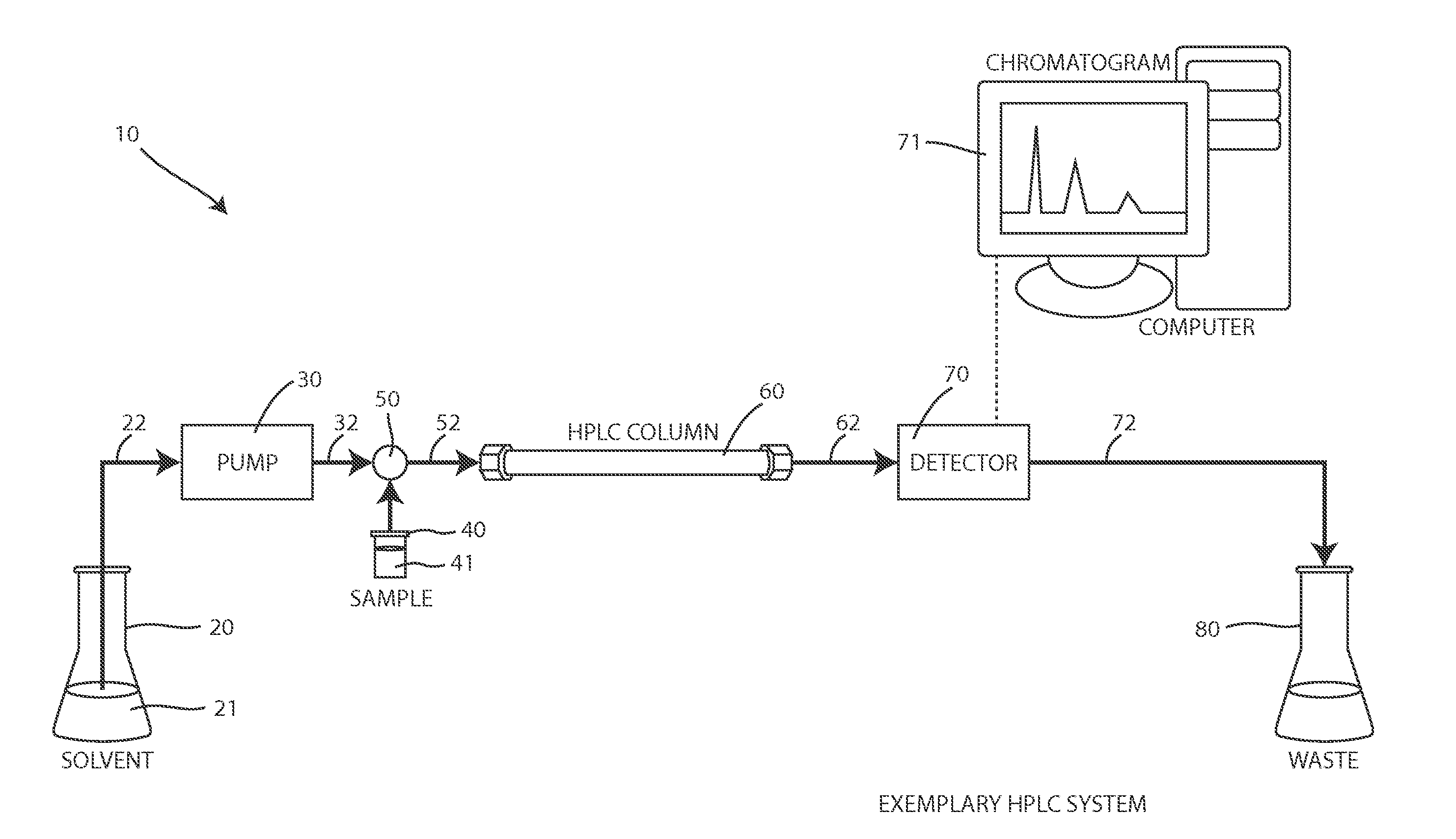
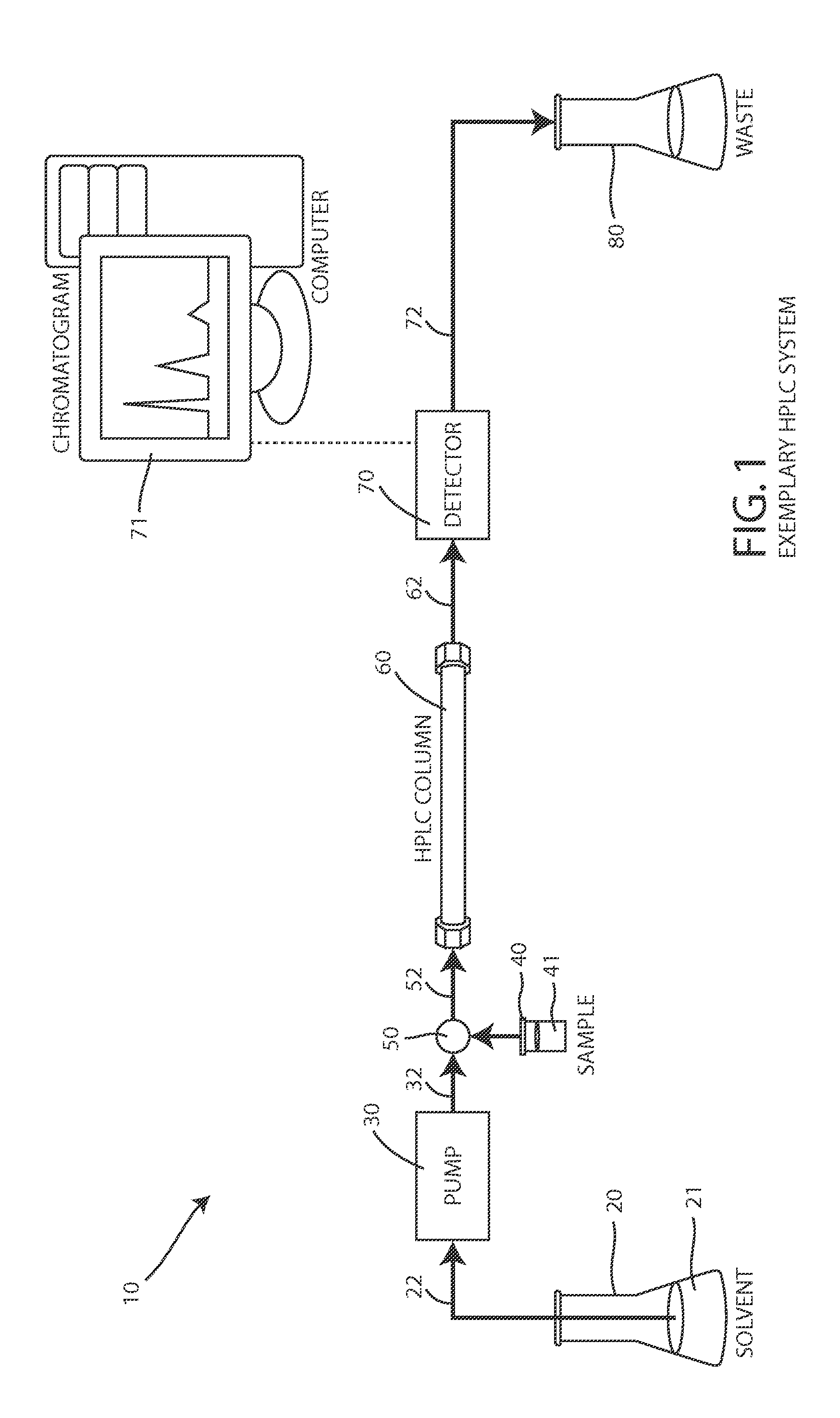
[0040]FIGS. 4A and 4B depict a first preferred embodiment of a flow rate measurement system 100 that uses a bubble injection system 110, a bubble detection system 150, and a suitable controller 170. As shown in FIG. 3, a primary fluid (e.g. solvent 21) is normally output by the primary pump 30 and is flowing through a conduit 32, 52, 62, 72 of the illustrated system 10. The bubble injection system 110 injects a small portion of an auxiliary fluid into the conduit to form an auxiliary fluid bubble that is trapped between a leading portion of the primary fluid and a trailing portion of the primary fluid. When the primary fluid continues flowing, the primary fluid moves the auxiliary fluid bubble through the conduit, within the bubble detection system 150, at the flow rate to be measured or verified. As explained below, the bubble detection system 150 detects the location of the auxiliary fluid bubble 140 (see FIG. 4B) as a function of time by detecting the detectable characteristic of...

second preferred embodiment

[0050]FIGS. 6A and 6B depict a second preferred embodiment of a flow rate measurement system 100′ that uses bubble injection system 110′ formed from a single, six-port, two-position valve, labeled “Valve X.” These rotary valves are often coupled to electromechanical controllers to rotate the internal valve mechanism clockwise or counterclockwise as desired, under the direction of a suitable controller 170. As shown in FIGS. 6A and 6B, the various Valve X ports are selectively connected to one of two adjacent ports depending on the valve position, e.g. 1-2, 3-4, 5-6 in Position A (Normal Flow), or 1-6, 2-3, 4-5 in Position B (Momentary Bubble Injection Mode via Air Loop Filling).

[0051]In this embodiment, a short piece of tubing 111 is coupled between port 6 and port 3 to form a loop that can uniquely pass the primary fluid or receive the auxiliary fluid or air. As shown by the heavier lines in FIG. 6A, when Valve X is in the NORMAL FLOW configuration of Position A, the primary liquid...


PUM


Abstract

A continuous, inline, flow rate measurement system for rapidly measuring a flow rate in an analytical instrument having a primary pump that outputs a primary fluid at the flow rate to be measured or verified. The flow rate measurement system includes an auxiliary pump that outputs an auxiliary fluid bubble having a detectable characteristic that is distinguishable from the primary fluid, a bubble injection system that injects a small portion of the auxiliary fluid into the conduit, and a bubble detection system for measuring the position of the auxiliary fluid bubble as a function of time based on a time of detecting the detectable characteristic of the auxiliary fluid, and a controller for converting the measured position of the auxiliary fluid bubble as a function of time into a volumetric flow rate based on a known volume of the conduit.

Description

BACKGROUND OF THE INVENTION[0001]1. Field of the Invention[0002]This application relates generally to analytical devices such as liquid chromatography systems and, more particularly, to an inline flow rate meter with auxiliary fluid injection and detection for measuring volumetric flow rates.[0003]2. Description of the Related Art[0004]Chromatography is used for separating a sample into its various components. In more detail, chromatography is a group of analytical methods for taking a sample (e.g. a complex mixture) and separating its component substances, or analytes, from one another. In general, analytical chromatography is used to determine the existence and sometimes the concentration of analytes in a sample.[0005]All chromatography systems involve two phases (states) of matter; a stationary phase and a mobile phase that carries the mixture through or past the stationary phase. The stationary phase is a solid and the mobile phase is a fluid, i.e. a liquid or a gas. As the mobi...

Claims


Application Information

Patent Timeline
Patent Type & Authority Patents(United States)
IPC IPC(8): G01F1/708G01F1/7086
CPCG01F1/708G01F1/7086G01N30/32G01N2030/324G01N30/02
Inventor NJAMFA, SERGE
Owner NJAMFA SERGE
Features
  • R&D
  • Intellectual Property
  • Life Sciences
  • Materials
  • Tech Scout
  • Unparalleled Data Quality
  • Higher Quality Content
  • 60% Fewer Hallucinations
Learn More