Scanning probe microscope and method of measurement

a scanning probe and microscope technology, applied in the direction of mechanical measurement arrangements, mechanical roughness/irregularity measurements, instruments, etc., can solve the problems of frictional force or attraction force, lower precision and reproducibility of measurement, etc., to achieve good reproducibility, simple control, and short time

Inactive Publication Date: 2005-04-19
NIHON KENKI CO LTD
View PDF21 Cites 35 Cited by
  • Summary
  • Abstract
  • Description
  • Claims
  • Application Information

AI Technical Summary

Benefits of technology

[0047]According to the method of measurement of the scanning probe microscope of the present invention, when performing wide measurement while approaching and separating the probe at a sampling position, by continuing servo control of the distance between the sample and probe based on the servo controller, the probe can be approached and separated by simple control in a short time.
[0048]Another scanning probe microscope of the present invention is configured as a microscope for wide measurement. The scanning probe microscope for wide measurement is provided with a movement mechanism (XY scanner) for making the probe scan the sample surface over a wide area, an approaching and separating device (for example, an approach and separation piezoelectric element and its drive) for making the probe approach to the sample surface at the sampling position and making the probe separate from the sample surface during movement between sampling positions, and an auxiliary movement mechanism (for example, an XY direction find movement part built in the piezoelectric element) for making the probe move in tandem at an equal speed in the same direction as the scan motion of the movement mechanism when making the probe approach to the sample surface for measurement at a sampling position. The movement mechanism is a main scanner causing scan motion by a large stroke at the time of measurement. The auxiliary movement mechanism is a sub scanner f...

Problems solved by technology

In this case, the force acting on the probe in the horizontal direction arising due to the frictional force and attraction force lowers the precision and reproducibility of measurement.
The above probe member suffers from problems due to being structured to contact the sample surface such as deformation or destruction of the sample surface or low resolution due to the mechanical contact structure.
Therefore, various problems such as the later mentioned frictional force or attraction force arise.
The frictional force or attraction force lowers the precision and reproducibility of measurement.
Even with this surface roughness meter, however, with just use of a cantilever of an atomic force microscope, possibility of reducing the reproducibility of measurement is high, so it is difficult to solve the above problem.
In such a configuration, similarly, the problem arises of the reduction in the reproducibility of measurement due to the above problems when extending or approaching the probe to the sample surface for measurement tracking the surface.
As a result, the problem arises that the force pressing against the probe 302 no longer becomes constant.
Therefore, such an external disturbance acts at topographic features inherently ...

Method used


Image

  • Scanning probe microscope and method of measurement
  • Scanning probe microscope and method of measurement
  • Scanning probe microscope and method of measurement

Examples


first embodiment

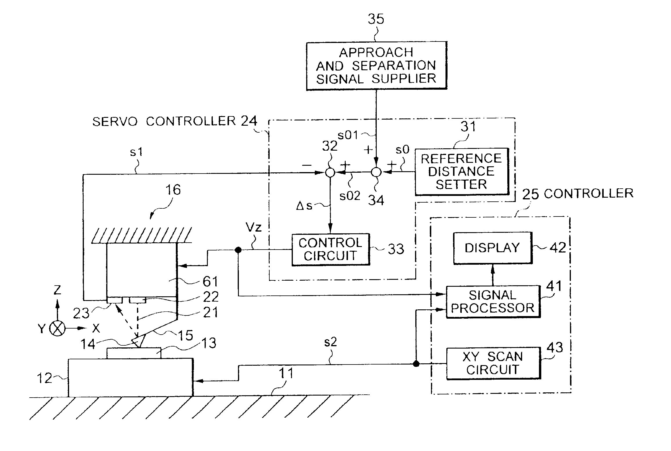
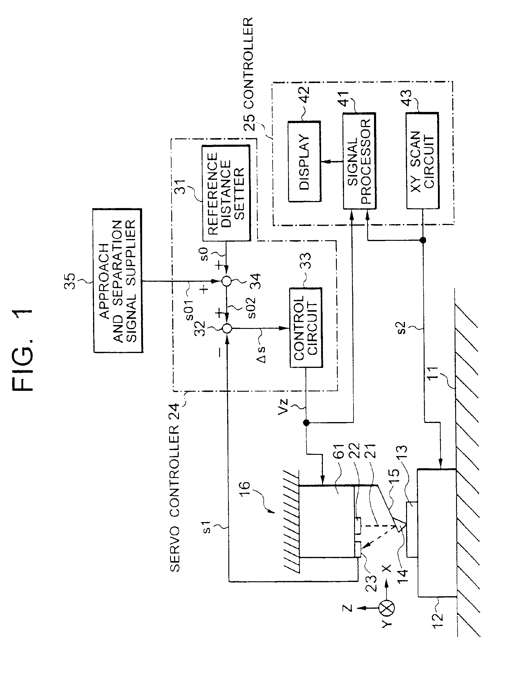
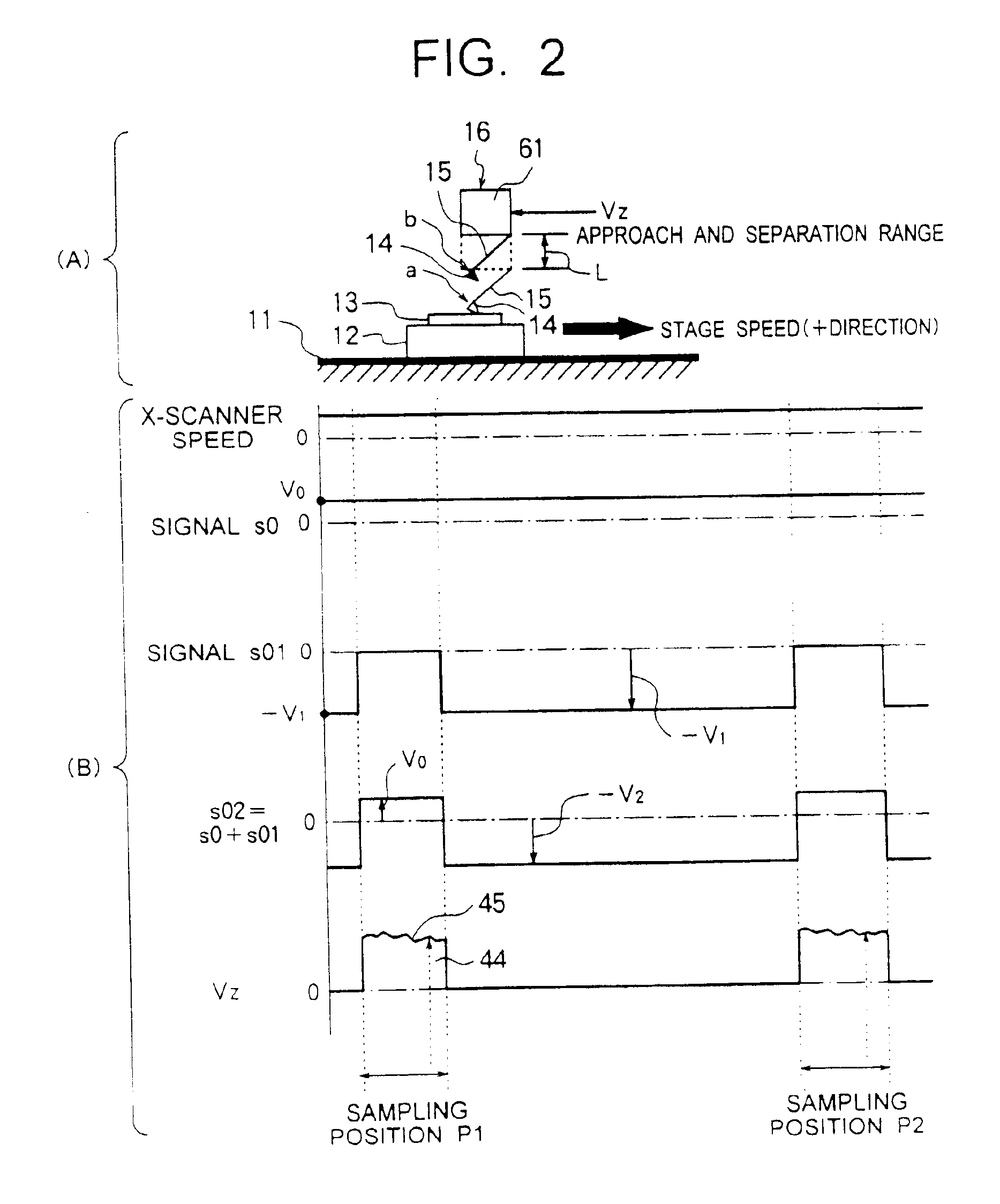
[0072]a scanning probe microscope according to the present invention will be explained with reference to FIGS. 1 and 2. FIG. 1 shows the configuration of the overall system of an atomic force microscope as a representative example of the scanning probe microscope. FIG. 2 shows the method of control of the positional change of the probe relating to approaching and separating movement, a timing chart, a waveform chart of voltage signals of parts at the time of probe movement in the X-direction and Z-direction, and the probe position in the height direction in the case of observing a specific area by the atomic force microscope while scanning the sample surface by the probe. The change in the position of the probe is caused by the scan of the probe in the XY directions along the sample surface and the movement in the height direction (Z-direction) for adjusting the distance between the sample and probe. Note that the X-direction, Y-direction, and Z-direction, as shown in FIG. 1, are th...

third embodiment

[0093]In the third embodiment, the Z-direction drive 16 is comprised of two piezoelectric elements 51, 52. The lower piezoelectric element 51 is a servo piezoelectric element engaged in the movement of the probe in the Z-direction. The piezoelectric element 51 is used as only a servo piezoelectric element for tracking the surface at the time of measurement. The upper piezoelectric element 52 is a piezoelectric element involved in only the approach and separation of the probe.

[0094]As shown in FIG. 4, in the third embodiment as well, the internal configurations of the servo controller 24 and the controller 25 are shown. The servo controller 24 is comprised of the reference distance setter 31 outputting the signal s0 for setting the reference distance, the subtractor 32 for calculating the difference As of the signal s1 and signal s0, and the control circuit 33 outputting the control signal Vz based on the difference Δs. Further, the controller 25 is provided with a signal processor 4...

fourth embodiment

[0097]Next, an explanation will be given of the scanning probe microscope according to the present invention with reference to FIGS. 6 and 7. This embodiment is predicated on wide measurement by a wide scan and involves a tandem movement when the probe is approached to the sample surface at the sampling positions.

[0098]FIG. 6 shows the overall system configuration of an atomic force microscope similar to the above as an example of a scanning probe microscope. In FIG. 6, the internal configurations of the servo controller 24 and controller 25 are not shown, but are similar to those of the previous embodiment. FIG. 8 is a timing chart of the relationship of speed for explaining the tandem movement of the probe in the X-direction. The change in the position of the probe is caused by the scan of the probe in the XY direction along the sample surface and the movement in the height direction (Z-direction) for adjusting the distance between the sample and probe. The X-direction, Y-directio...


PUM


Abstract

A scanning probe microscope has an XY scanner for making a probe scan a sample surface, an approach and separate drive element for making the probe approach to the sample surface at a sampling position and separate the probe from the sample surface during movement between the sampling positions, and a servo controller for holding the distance between the probe and the sample surface at a reference distance during measurement at the sampling position. A plurality of scattered measurement locations are set away from each other as sampling positions. The approach and separation movements are performed at each sampling position. When measuring the surface by the probe at a sampling position and while making the probe move between sampling positions, servo control by the servo controller is continued. This makes it possible to quickly measure the surface by a simple controller and possible to measure a wide area or measure a high aspect ratio. When making the probe approach to the sample surface for measurement at the sampling position, it is also possible to cause a scan motion for tandem movement at an equal speed and in the same direction as the scan motion by the XY scanner.

Description

BACKGROUND OF THE INVENTION[0001]1. Field of the Invention[0002]The present invention relates to a scanning probe microscope and a method of measurement capable of measuring objects with a high aspect ratio or a wide-area scanning by approaching and separating a probe to and from a sample surface while continuing a servo control for the probe in a measurement by an atomic force microscope for example. More particularly the scanning probe microscope of the present invention is useful for enlarging the field of observation for evaluation of polishing in chemical mechanical polishing (CMP) to the millimeter class, which is highly needed in the field of the production of semiconductors.[0003]2. Description of the Related Art[0004]Representative examples of the scanning probe microscope are atomic force microscopes, magnetic force microscopes and tunnel microscopes. An atomic force microscope is utilized for measuring the topography of the surface of a semiconductor substrate, for exampl...

Claims


Application Information

Patent Timeline
IPC IPC(8): G01N23/00H01J37/26G01Q20/04G01Q60/00
CPCB82Y35/00G01Q30/06G01Q10/06Y10S977/851
Inventor MORIMOTO, TAKAFUMIKURODA, HIROSHI
Owner NIHON KENKI CO LTD
Why Eureka
Try Eureka