
Fluid-cooled electric machine

a technology of electric machines and fluids, applied in the direction of cooling/ventilation arrangement, magnetic circuit rotating parts, shape/form/construction, etc., can solve the problems of hot spots and fluid only being actively conveyed, and achieve the effect of improving the fluid cooling of electric machines

Inactive Publication Date: 2016-03-29
SIEMENS AG
View PDF28 Cites 4 Cited by
  • Summary
  • Abstract
  • Description
  • Claims
  • Application Information

AI Technical Summary

Benefits of technology

This patent describes an electric machine with a cooling system using a fluid such as oil or water. The machine has a pump to circulate the fluid through the machine and cool it. This improves the machine's performance without the need for an external pump. The cooling system also helps to prevent the fluid from boiling in the air gap between the stator and rotor. Additionally, the patent discusses a conical positioning of the stator winding and air gap, which helps to maintain a constant distance between them. Overall, this patent provides a simple and effective solution for cooling electric machines.

Problems solved by technology

If the oil is situated in the air gap of the electric machine, hot spots can occur there.
This is due in particular to the heat produced by the rotor and high friction losses.
This means that fluid is only actively conveyed (pumped) within the electric machine when the electric machine performs a rotational movement.

Method used


Image

  • Fluid-cooled electric machine
  • Fluid-cooled electric machine
  • Fluid-cooled electric machine

Examples


Embodiment Construction

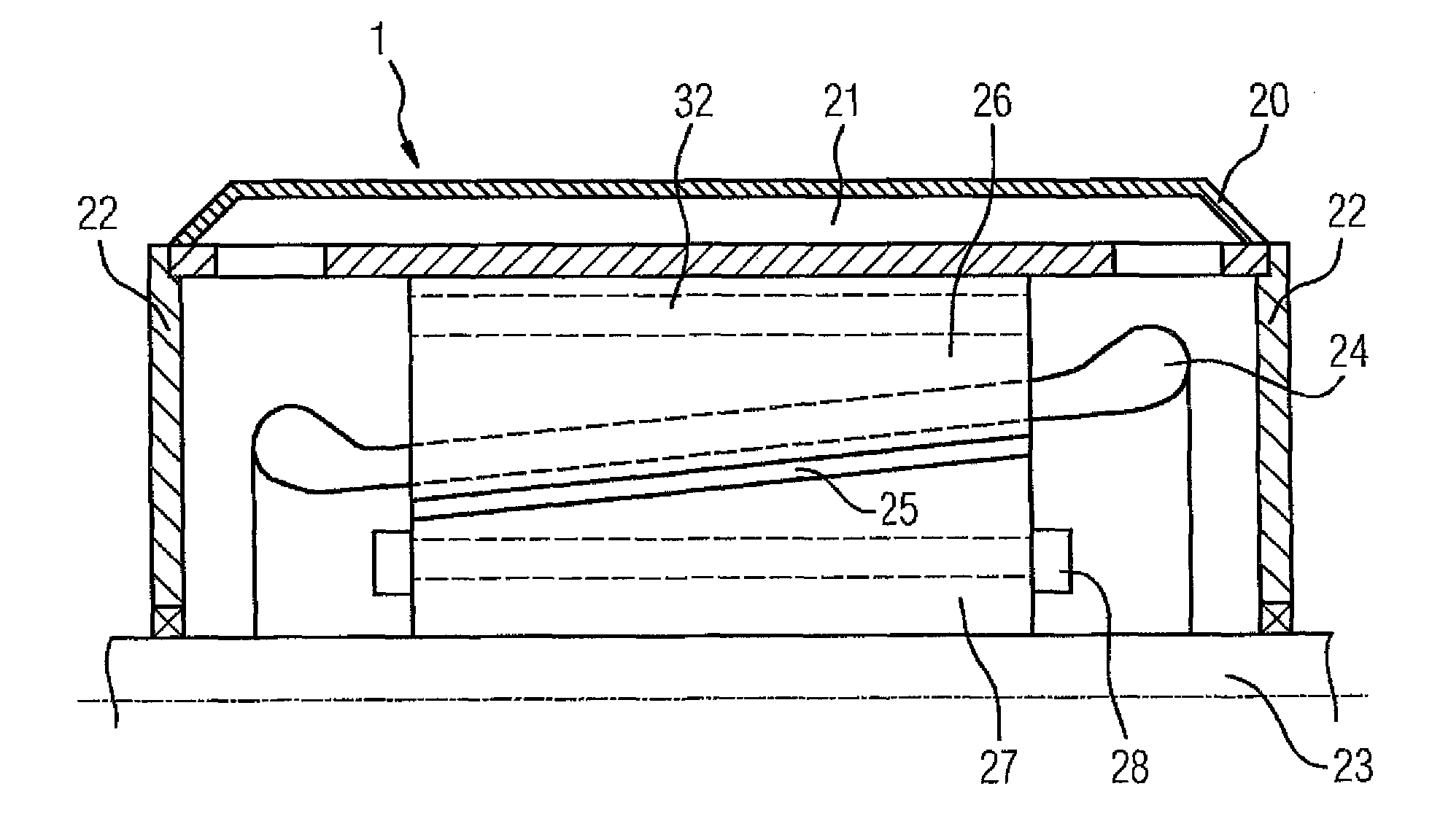
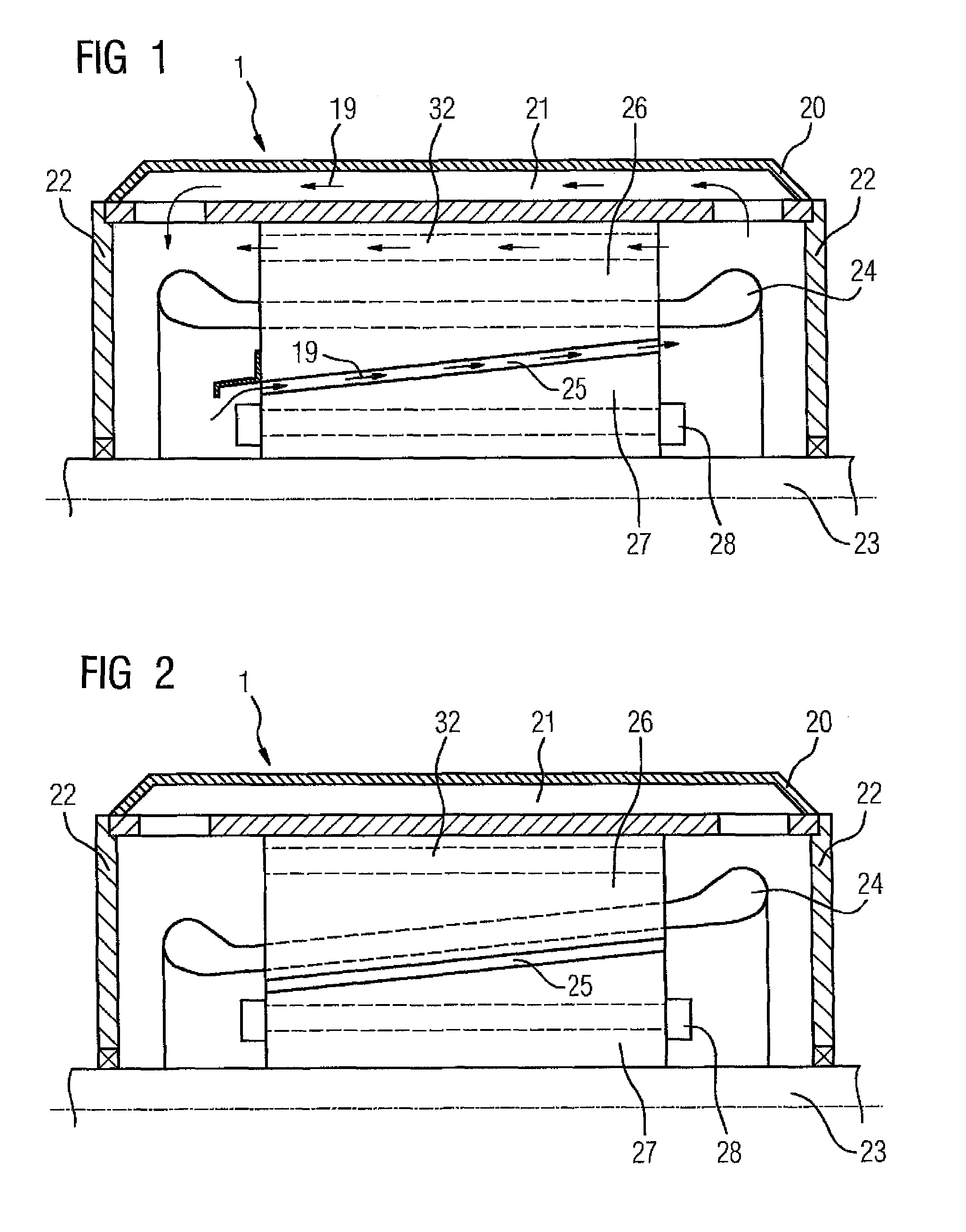
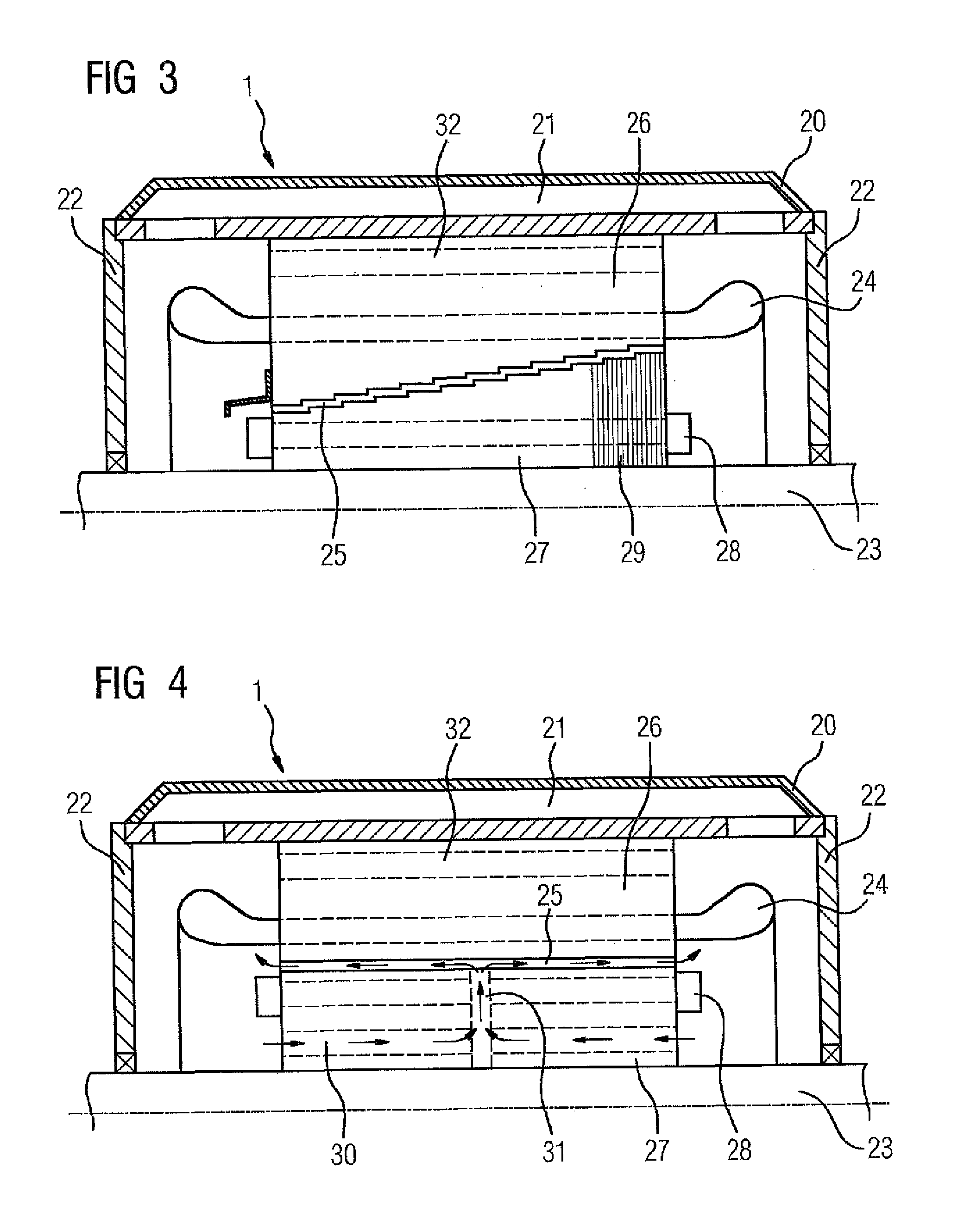
[0033]The illustration according to FIG. 1 shows a partial section through an electric machine 1. The electric machine 1 comprises a stator 26 and a rotor 27. An air gap 25 between rotor 27 and stator 26 is conically positioned within the electric machine 1, such that the distance from the air gap 25 to a shaft 23 changes axially. The electric machine 1 according to FIG. 1 further comprises bearing shells 22 and a hollow rib 20, wherein fluid, in particular cooling liquid, can be carried thorough the cooling channel 21 in the hollow rib. The circuit of the fluid is illustrated by means of arrows 19. The fluid is conveyed axially through the electric machine 1 via the air gap 25 and returned via the channel 21 in the cooling rib 20 and a stator channel 32. By virtue of this circulation of the fluid, which is e.g. oil, both the stator 26 and the rotor 27 of the electric machine 1 are cooled. In the present case, the rotor 27 comprises a cage winding 28.

[0034]Further embodiments of an ...


PUM


Abstract

A fluid-cooled electric machine includes a fluid circuit and an integrated pump element which executes a pumping action to conduct fluid through the fluid circuit as a result of a rotational movement of the electric machine. The electric machine includes a stator and a rotor arranged to demarcate with the stator a conical air gap which is flooded with fluid.

Description

CROSS-REFERENCES TO RELATED APPLICATIONS[0001]This application is the U.S. National Stage of International Application No. PCT / EP2011 / 059844, filed Jun. 14, 2011, which designated the United States and has been published as International Publication No. WO 2012 / 013412 and which claims the priority of German Patent Application, Serial No. 10 2010 038 529.8, filed Jul. 28, 2010, pursuant to 35 U.S.C. 119(a)-(d).BACKGROUND OF THE INVENTION[0002]The invention relates to an electric machine that can be cooled by means of a fluid. A fluid is e.g. an oil, water, a high-density gas or a high-density refrigerant.[0003]Various mediums can be used for cooling electric machines. If air is used, the electric machine can be cooled by means of an external ventilator or an integrated ventilator. Electric machines can also be cooled by means of a liquid. Examples of liquids include water or an oil.SUMMARY OF THE INVENTION[0004]The object of the present invention is to improve the fluid cooling of an...

Claims


Application Information

Patent Timeline
IPC IPC(8): H02K9/00H02K1/32H02K9/19H02K9/10H02K1/20
CPCH02K9/005H02K1/32H02K9/10H02K9/19H02K1/20H02K2201/03H02K9/00
Inventor HAUTZ, RUDOLFNEUPERT, KLAUSOBERMAYR, MARTINSTARK, MARTINWATZINGER, JOSEFZWACK, JOSEF
Owner SIEMENS AG
Learn More