Pump system and agricultural sprayer pump system

a pump system and pump technology, applied in the field of pump systems, can solve the problems of difficult cleaning, complex pipe network and valve arrangement, etc., and achieve the effect of compact arrangemen

Active Publication Date: 2016-04-05
AGCO NETHERLANDS
View PDF6 Cites 1 Cited by
  • Summary
  • Abstract
  • Description
  • Claims
  • Application Information

AI Technical Summary

Benefits of technology

[0013]By integrating a portion of the suction side ball valve casing with the pump casing in a unitary casting a number of benefits are provided. Firstly, the number of components required to form the suction side distribution valve and the pump is reduced thereby saving cost in manufacture. Secondly, the suction side distribution valve is located immediately up-stream of the pump thereby providing a more compact arrangement. Thirdly, the close proximity of the ball valve to the pump impellor delivers a more efficient fluid flow as the fluid enters the pump housing along the rotation axis of the impellor. Fourthly, the plumbing is easier to rinse because the number of corners and disturbances is reduced.
[0014]The pump system preferably comprises a suction side manifold in sealing connection with said portion of the ball valve casing. The suction side manifold provides a further portion of the ball valve casing and comprises a number of inlet pipes that correspond to the valve inlet ports and which align with a bore provided in the ball of the valve. The suction side manifold may be formed from a single casting thereby saving further cost and component numbers. Together with the casting of the pump housing, the suction side manifold provides a casing for the ball valve together with pipe connections for the inlet ports. The valve bore is preferably of a bent L-shape to place a selected one of the inlet ports and the suction side of the pump into fluid communication.
[0015]The pump system may further comprise a filter housing mounted to the centrifugal pump, the filter housing having an inlet plumbed to a coupling device for attaching a filler hose, and an outlet plumbed to a first one of said plurality of inlet pipes of the suction side manifold. The filter housing may be associated with a filling line which is, advantageously, provided in the vicinity of the pump making for a more compact system. The suction side manifold provides a direct connection from the suction side distribution valve to the filler line filter without the need for additional pipework. Not only does this reduce the number of components required but a more robust arrangement is provided.
[0016]The sprayer may comprise an operator work station having a console which includes an access opening to the filter housing for the operator to replace filter element. By providing the filter housing under the console the ergonomics of routine replacement of the filter are improved.
[0021]The outlet pipes may be connected to one or more fluid consumers on the sprayer including, by way of example, the nozzles of the spray boom, the main storage tank, the clean water tank, and an unloading hose connection. A pressure side filter may be provided having a housing mounted to the centrifugal pump wherein the filter housing has an inlet plumbed to one of said plurality of outlet pipes of the pressure side manifold. Advantageously, the pressure side filter is provided in the vicinity of the pump making for a more compact arrangement.

Problems solved by technology

The overall pump system may, therefore, include a multitude of components including valves, filters, joints and pipes spread over the vehicle thus demanding complex pipe networks and valve arrangements.
The complex arrangements present many corners and “dead spots” where chemicals can become trapped making it difficult to clean.

Method used


Image

  • Pump system and agricultural sprayer pump system
  • Pump system and agricultural sprayer pump system
  • Pump system and agricultural sprayer pump system

Examples


Embodiment Construction

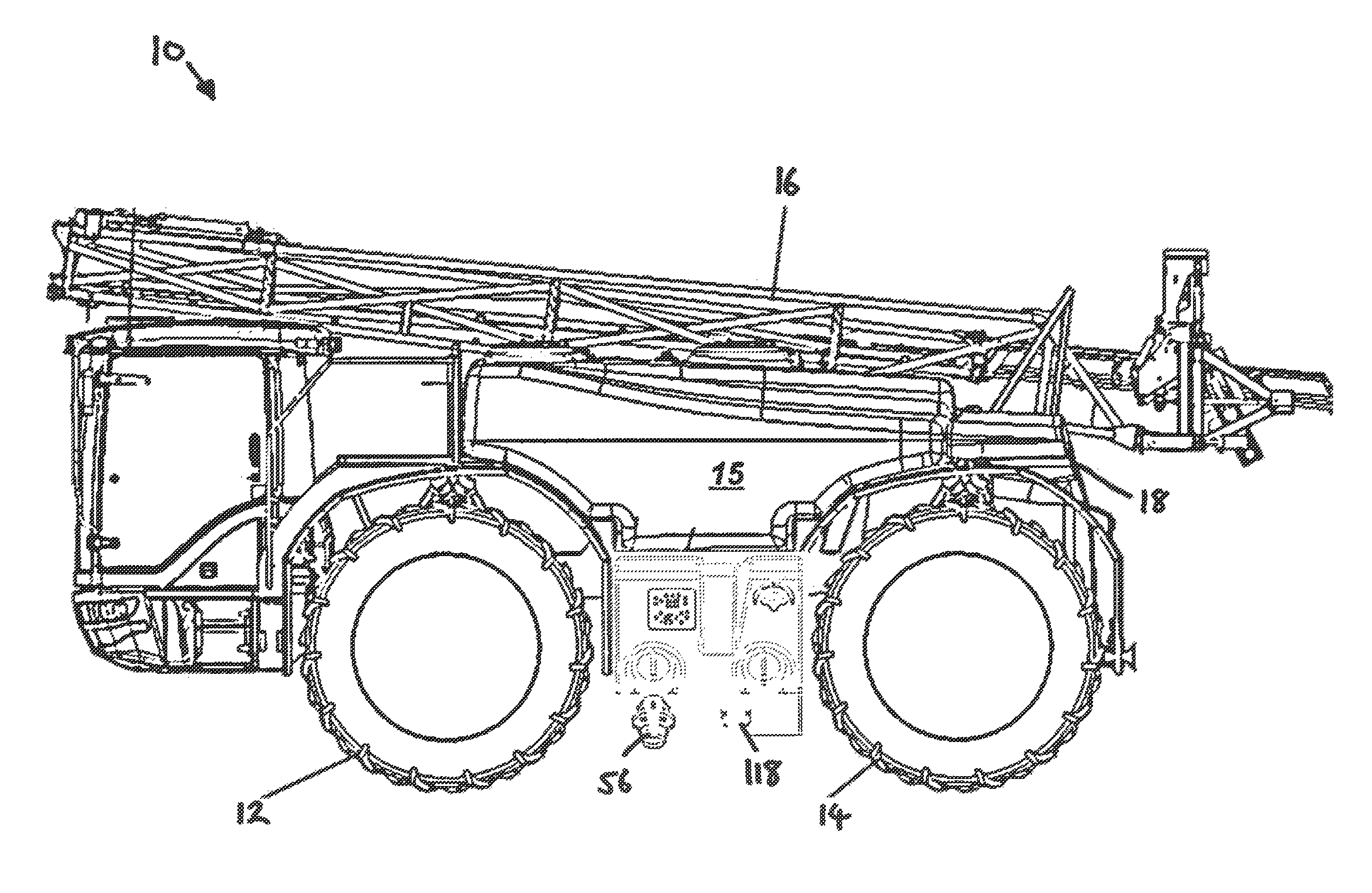
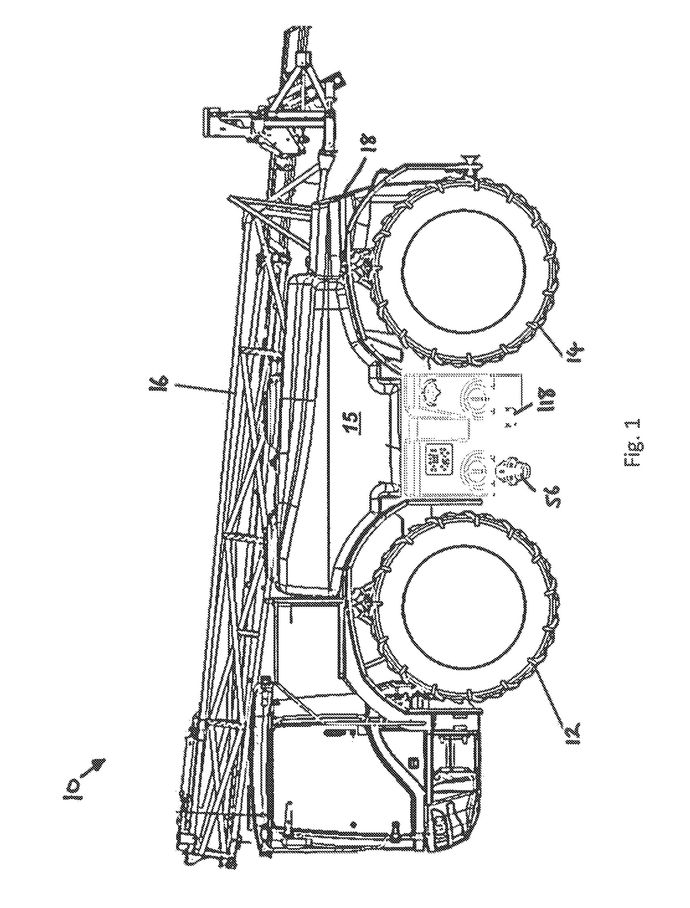
[0038]With reference to FIG. 1 a self-propelled agricultural sprayer 10 comprises front wheels 12 and rear wheels 14. An on-board main storage tank 15 serves to store the pesticide or nutrient solution for application to the field. A spray boom 16 (shown in a folded state) extends transversely relative to the forward direction of travel and includes a number of spray nozzles for applying the solution. An auxiliary, clean water, tank 18 is also provided for storing a volume of clean water which is used to rinse the plumbing and main tank 15 after the spraying operation.

[0039]Although a self-propelled application machine is shown and described hereinafter, it should be understood that the embodied invention is applicable to other agricultural sprayers including pull-type (towed) sprayers and (3-point linkage) mounted sprayers.

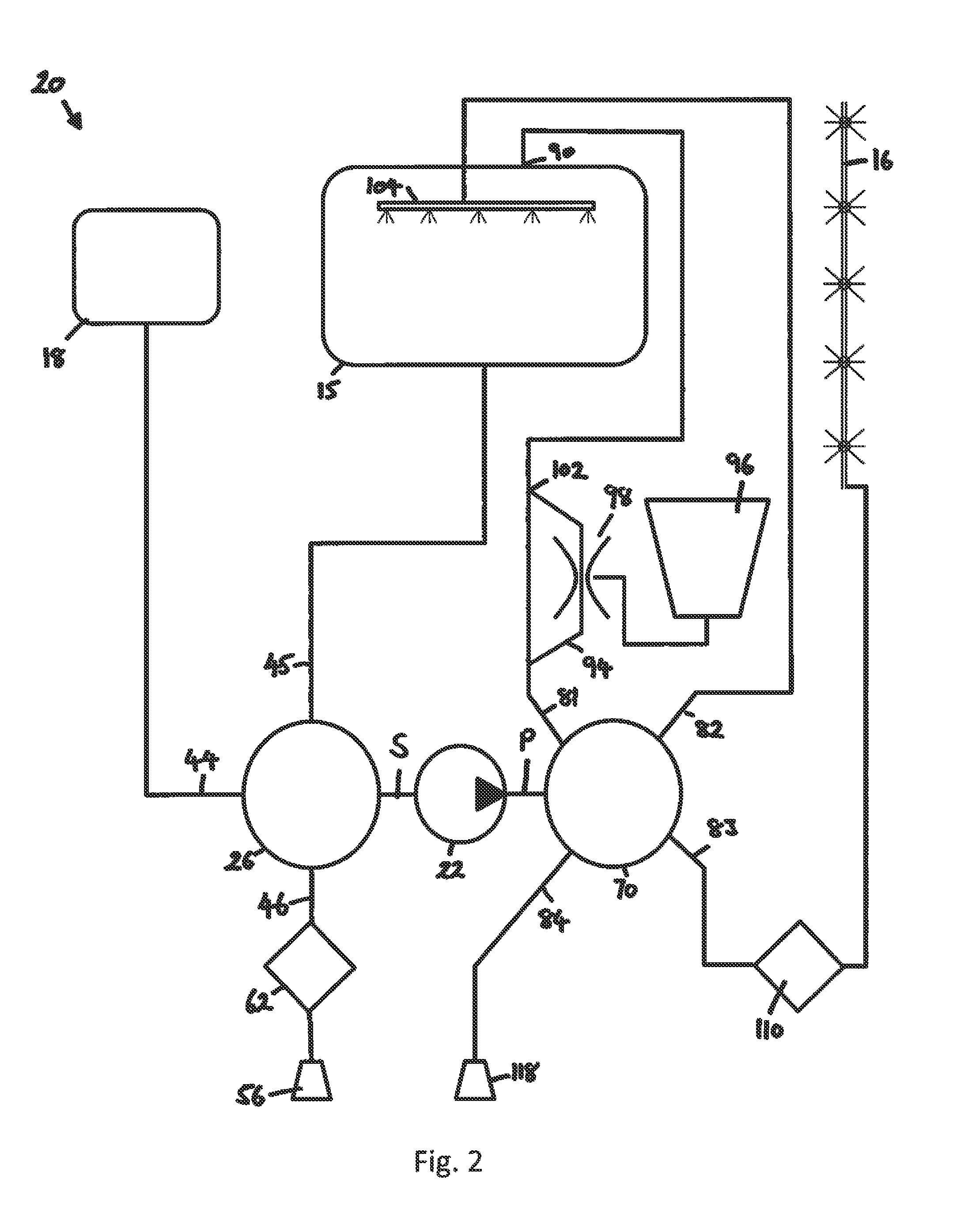
[0040]With reference to FIG. 2, a pump system 20 serves to convey and distribute fluid between the various fluid sources and consumers. With reference also to FI...


PUM


Abstract

An agricultural sprayer comprises a pump system for conveying and distributing fluid between fluid sources and consumers. The pump system comprises a centrifugal pump and a multi-inlet ball valve located on a suction side of the pump. The centrifugal pump comprises an impeller that rotates on a pump axis. The ball valve comprises a ball that is rotatable around the pump axis to selectively connect the valve inlets to the pump. The pump comprises a pump casing that is provided together with a portion of a ball valve casing by a unitary casting.

Description

BACKGROUND OF THE INVENTION[0001]1. Field of Invention[0002]The invention relates to pump systems for agricultural sprayers which serve to distribute fluid between various fluid sources and consumers including tanks, water supplies and spray booms.[0003]2. Description of Related Art[0004]Agricultural sprayers are employed by farmers and contractors alike to apply to a crop field pesticides and / or nutrients in the form of liquid solutions. A sprayer typically comprises a main tank for storing the liquid to be applied and a plurality of liquid application nozzles arranged along a boom, the boom extending in a direction transverse to the forward direction of travel. An on-board pump system serves to pump the fluid from the tank to the nozzles during operation.[0005]In addition to the main tank and spray nozzles, the pump system may also serve to convey fluid between other sources and consumers. For example, in a fill mode, the pump may drive water from an external source to the main ta...

Claims


Application Information

Patent Timeline
Patent Type & Authority Patents(United States)
IPC IPC(8): B05B1/20A01M7/00B05B12/14A01C23/04F04D29/02F04D29/42F16K27/06F16K11/087F04D15/00
CPCA01M7/005A01C23/047A01M7/00B05B12/14F04D15/0016F04D29/026F04D29/4293F16K11/0873F16K27/067Y10T137/4259Y10T137/794Y10T137/85986Y10T137/86027F05D2230/60F05D2230/53
Inventor HIDDEMA, JORIS JAN
Owner AGCO NETHERLANDS
Why Eureka
Try Eureka