
Method and device for operating a hybrid vehicle in the event of a fault in an energy system

a technology of hybrid vehicles and energy systems, applied in electric devices, battery/fuel cell control arrangements, electric machines, etc., can solve the problems of draining the battery, no longer providing high voltage to the electric machine, and no longer being able to recharge the high voltage battery

Active Publication Date: 2016-04-05
ROBERT BOSCH GMBH
View PDF16 Cites 6 Cited by
  • Summary
  • Abstract
  • Description
  • Claims
  • Application Information

AI Technical Summary

Benefits of technology

This patent describes a method for operating a hybrid vehicle in case of a fault in the energy system. The method involves using an electric power plant to maintain the energy supply to control units in the vehicle. The electric power plant operates in a safe mode to prevent injury to operators. The method also includes monitoring the high voltage mechanical cover to detect any faults and quickly detecting and addressing any issues in the high voltage energy system. The electric power plant may switch the vehicle's electrical system from torque to voltage regulation to provide sufficient energy to operate the vehicle in case of a fault. The technical effects of this patent are improved safety and reliability of the hybrid vehicle during emergency situations and reduced complexity and cost compared to previous solutions.

Problems solved by technology

Consequently, the electric machine is no longer supplied with high voltage, and the high voltage battery may no longer be recharged.
Over time, this drains the battery of the low voltage energy system, which supplies the control units of the hybrid vehicle with energy.
If energy is not supplied to the control units, the hybrid vehicle may no longer be operable after a certain amount of time.
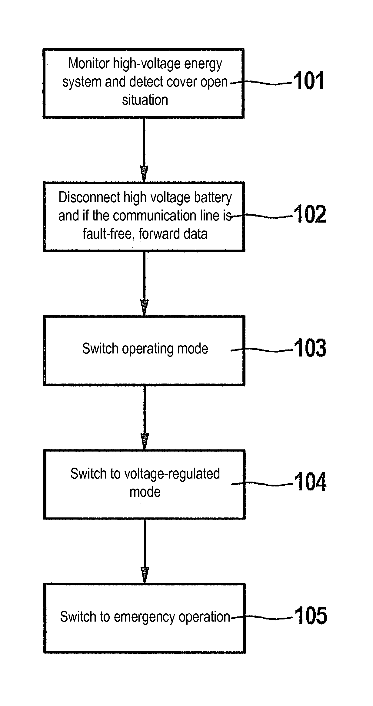
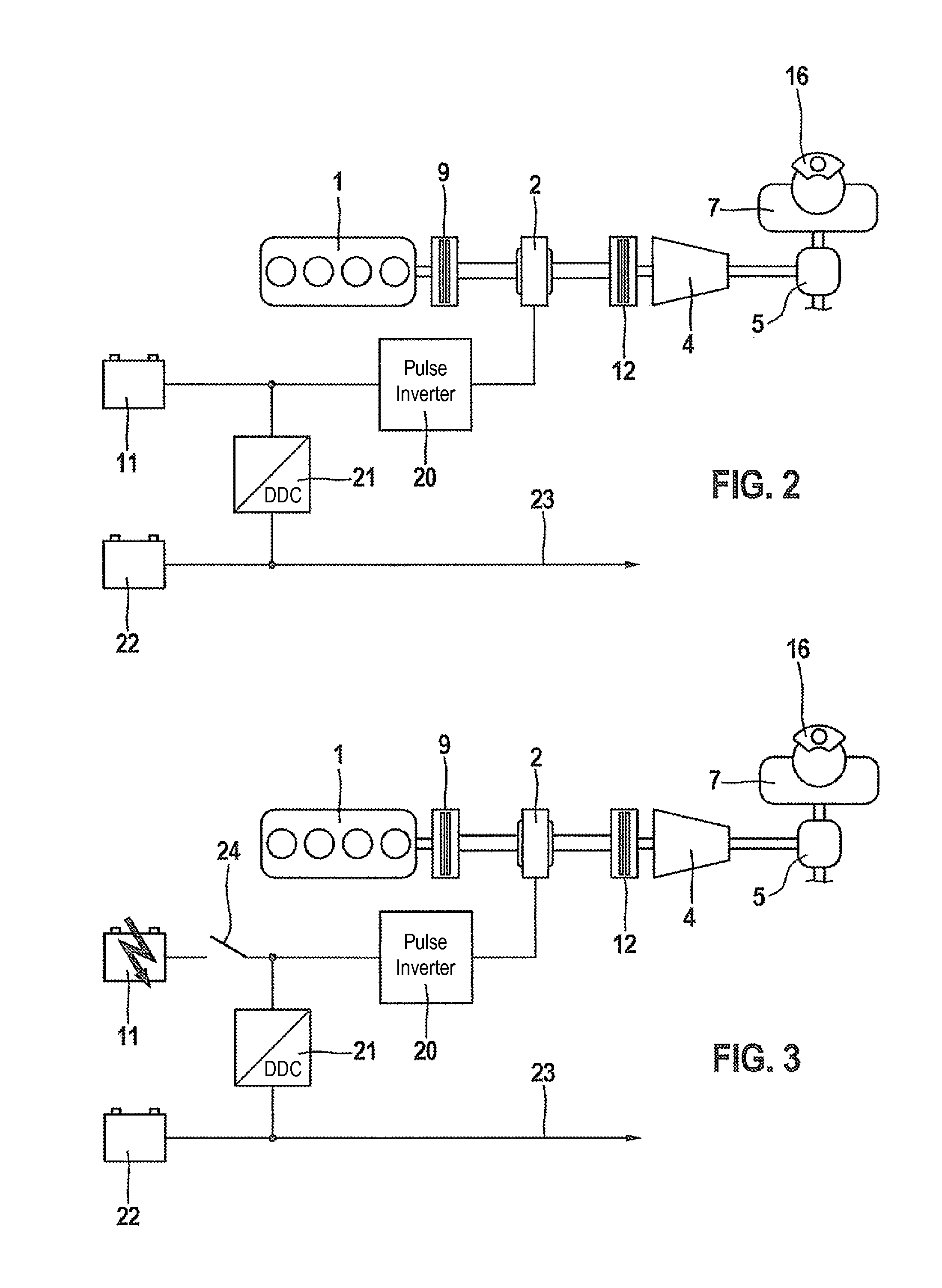
Due to the fact that the electric power plant is placed in a state for generating a voltage which is uncritical for the safety of the user after the high voltage energy system is disconnected, the safety-uncritical voltage being converted into the low voltage for supplying the at least one control unit, an emergency operation of the hybrid vehicle is possible at any time even in the event of a fault in the high voltage energy system.

Method used


Image

  • Method and device for operating a hybrid vehicle in the event of a fault in an energy system
  • Method and device for operating a hybrid vehicle in the event of a fault in an energy system
  • Method and device for operating a hybrid vehicle in the event of a fault in an energy system

Examples


Embodiment Construction

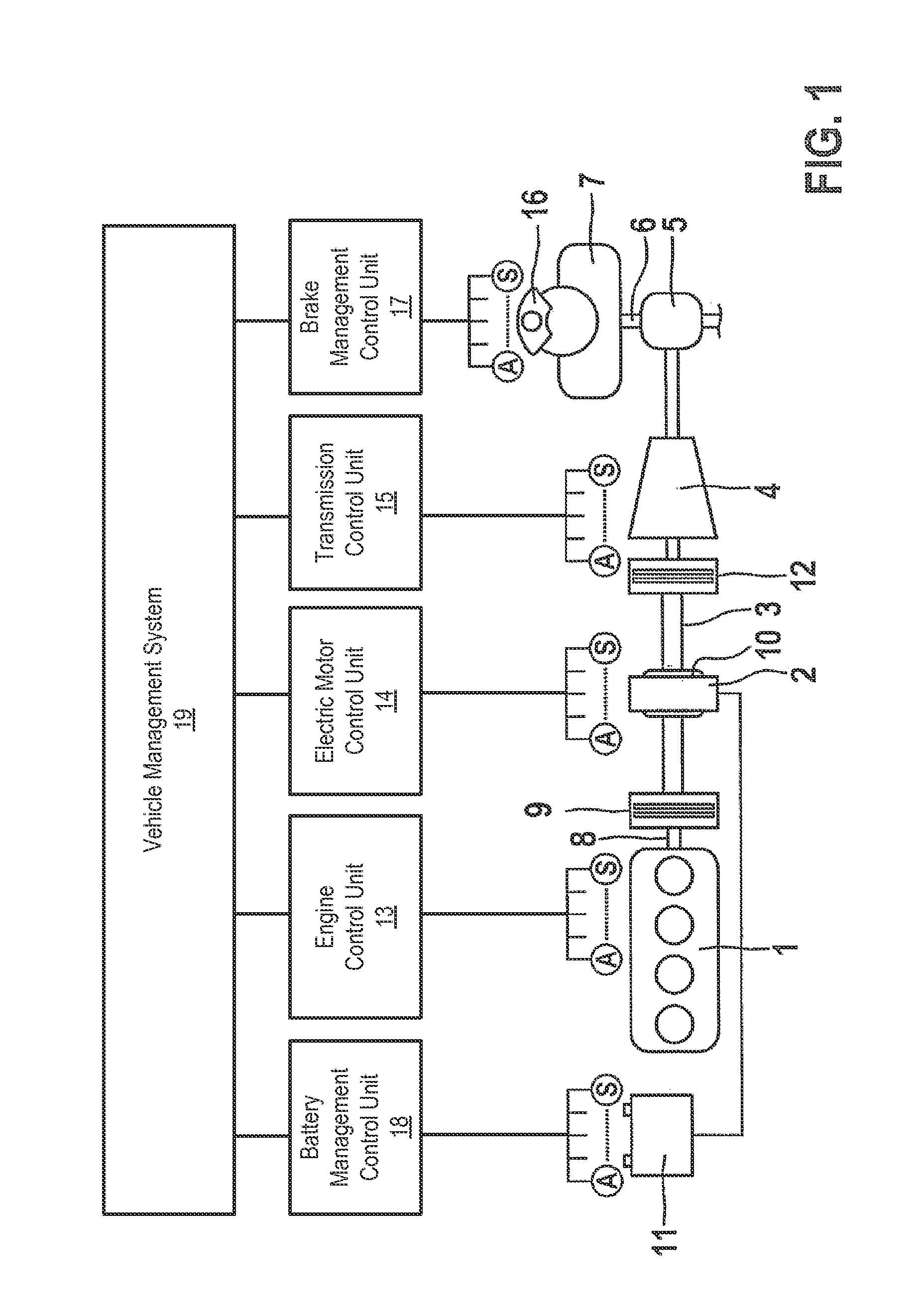
[0025]FIG. 1 shows a schematic representation of a vehicle which has a parallel hybrid drive. The hybrid drive is formed by an internal combustion engine 1 as the first drive unit and an electric motor 2 as the second drive unit.

[0026]Internal combustion engine 1 is connected via drive train 3 to transmission 4, which, in turn, leads to wheel axle 6 for driving wheel 7 via differential gear 5.

[0027]Electric motor 2 is situated on shaft 8 of internal combustion engine 1 and thus also leads to drive train 3, which is connected to transmission 4. A starting clutch 12, which connects drive train 3 to the transmission for starting the vehicle movement of the vehicle, is situated between transmission 4 and drive train 3. Electric motor 2 thus contributes to the driving of wheels 7 and to the total torque of the vehicle. Electric motor 2 and internal combustion engine 1 are connected to each other via a separating clutch 9. In the disengaged state, this separating clutch 9 enables the vehi...


PUM


Abstract

A method for operating a hybrid vehicle, the vehicle being driven by at least two power plants, and at least one electric power plant charging a high voltage energy system which supplies a low voltage energy system with electrical energy, a high voltage being converted into a low voltage for supplying at least one control unit of the vehicle, and the vehicle being disconnected from the electric power plant when a fault is detected in the high voltage system. To maintain the energy supply to the control units via the low voltage system even in the event of a fault in the high voltage system, the power plant is placed in a state for generating a voltage which is uncritical for the safety of the user after the high voltage system is disconnected, the safety-uncritical voltage being converted into the low voltage for supplying the at least one control unit.

Description

FIELD OF THE INVENTION[0001]The present invention relates to a method for operating a hybrid vehicle in the event of a fault in an energy system, the hybrid vehicle being driven by at least two power plants, together or separately, and at least one electric power plant electrically charging a high voltage energy system which supplies a low voltage energy system with electrical energy, a high voltage being converted into a low voltage for supplying at least one control unit of the hybrid vehicle; the present invention also relates to a device for carrying out the method.BACKGROUND INFORMATION[0002]Vehicles which have a hybrid drive structure include an internal combustion engine and usually at least one electric motor as the second power plant. The driving torque may thus be generated by both power plants during operation of the hybrid vehicle. The electric drive is connected to an energy storage which supplies the electric drive with electrical energy. When the internal combustion e...

Claims


Application Information

Patent Timeline
Patent Type & Authority Patents(United States)
IPC IPC(8): B60L9/00B60L11/18B60L11/14B60K6/48B60L3/00B60L3/04B60L50/15B60L50/16
CPCB60L11/14B60K6/48B60L3/0069B60L3/0092B60L3/04B60L11/1868Y02T10/6221Y02T10/70Y02T10/7005Y02T10/7066Y02T10/7077B60L50/16B60L58/20Y02T10/62Y02T10/7072B60W10/26B60W20/50B60W50/02B60Y2200/92
Inventor SCHNEIDER, NORBERTLEHNER, MICHAEL
Owner ROBERT BOSCH GMBH
Learn More