Roller shade system and method

a shade system and roller technology, applied in the direction of door/window protection devices, coupling-brake combinations, constructions, etc., can solve the problems of uneven effort to operate the shade, unfavorable protection, and cancelling moments that require additional force to overcome, so as to achieve less friction and less force. , the effect of smoother operation

Active Publication Date: 2016-04-05
CIERA IND
View PDF19 Cites 18 Cited by
  • Summary
  • Abstract
  • Description
  • Claims
  • Application Information

AI Technical Summary

Benefits of technology

[0007]The present invention is directed to improvements over prior art roller shade systems, and provides for smoother operation with less friction, thus requiring less force by a user.
[0008]It is an object of this invention to provide a window shade assembly with better engagement between the clutch and the clutch bracket.
[0011]It is also an object of this invention to provide a better way of engaging an idler in an idler bracket, as well as to provide adjustability to the idler bracket allowing for easy height adjustment of the idler.

Problems solved by technology

This uneven load distribution during rotation causes uneven friction and uneven effort to operate the shade.
Additionally, the use of an even number of springs creates a cancelling moment that requires added force to overcome.
Such variations inhibit smooth raising and lowering of the shade.
Prior roller shade systems suffered from other defects, such as wobbly or hard to connect clutch and idler brackets.
Moreover, prior roller shade systems are difficult to mount level and if mounted even slightly out of level may lead to obviously misaligned shades when the shades are lowered.

Method used


Image

  • Roller shade system and method
  • Roller shade system and method
  • Roller shade system and method

Examples


Embodiment Construction

[0032]In the following description of the preferred embodiments, reference is made to the accompanying drawings which show by way of illustration specific embodiments in which the invention may be practiced. Wherever possible, the same reference numbers will be used throughout the drawings to refer to the same or like parts. It is to be understood that other embodiments may be utilized and structural and functional changes may be made without departing from the scope of the present invention.

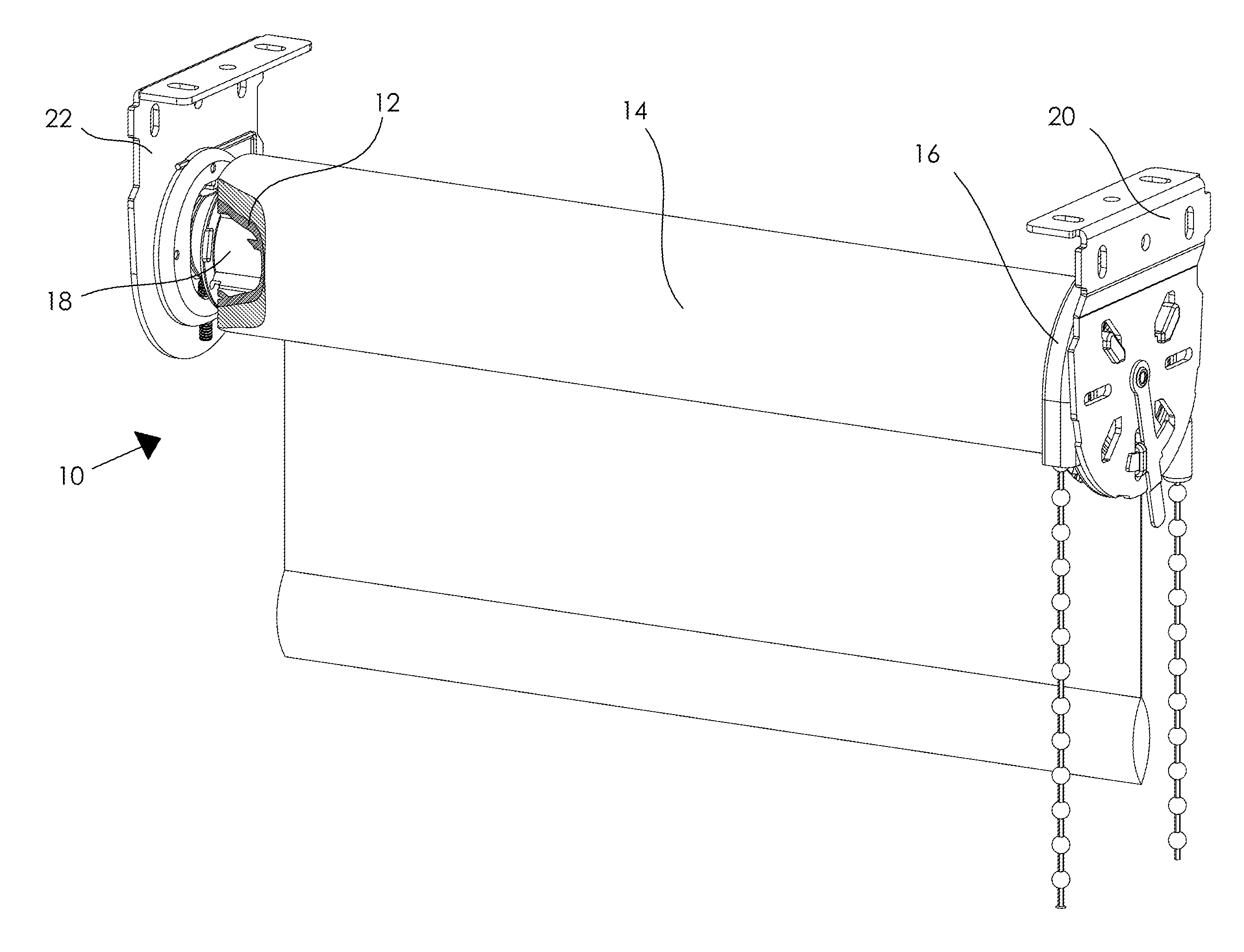
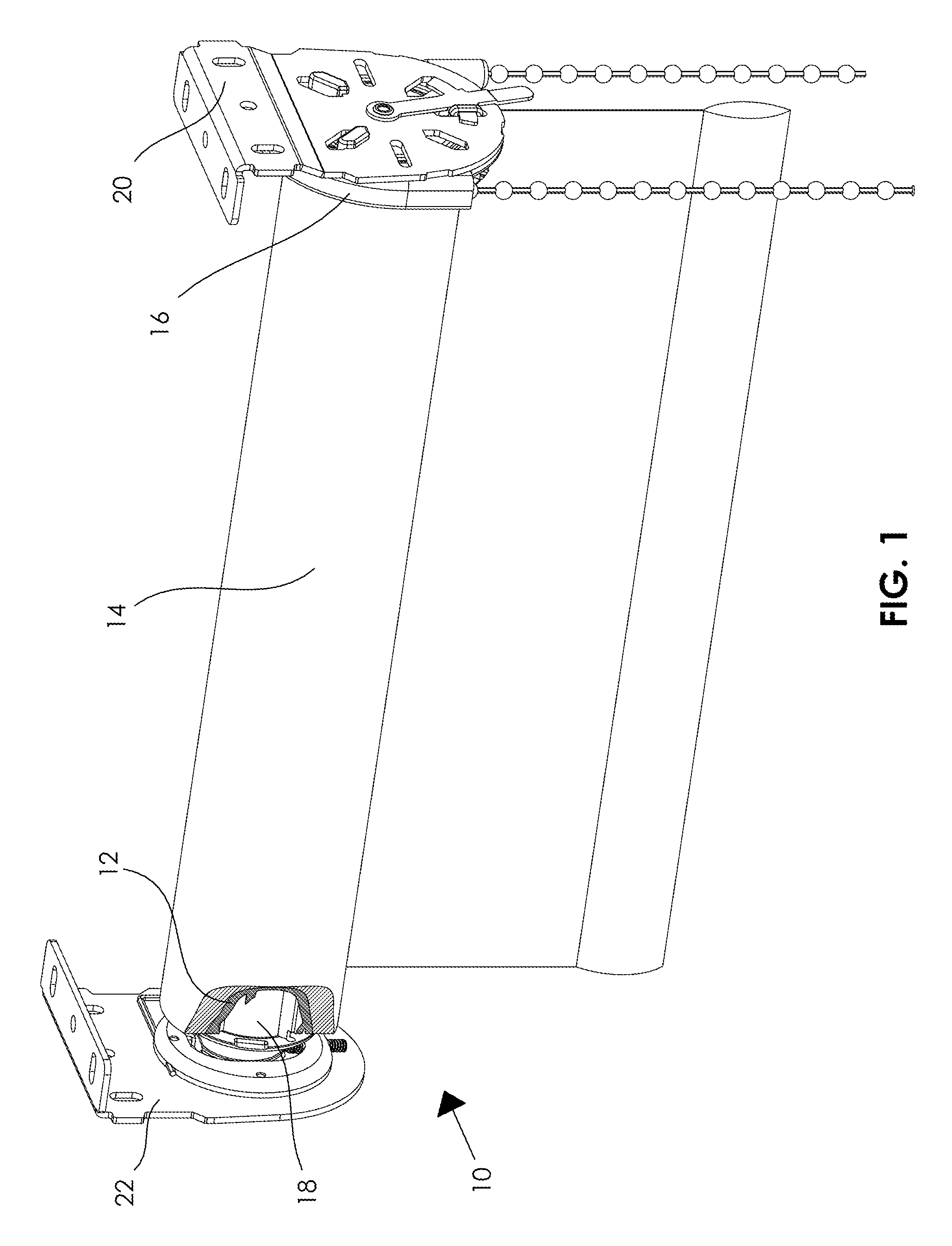
[0033]With reference to FIG. 1, the present invention, according to an embodiment, is directed to a roller shade system 10 for lifting and lowering a roller shade. The system includes a tube 12 for holding a shade 14. A clutch assembly 16 is mated to a first side of the tube 12 and an idler assembly 18 is mated to a second side of the tube 12. The clutch assembly 16 is connectable to a clutch bracket 20. The idler assembly 18 is rotatably connectable to an idler bracket 22. The various component...


PUM


Abstract

An apparatus for raising and lowering a window shade having: a clutch assembly with a clutch core having a shaft; springs having pairs of load bearing members, the springs being circumferentially positioned along a length of the shaft, the pairs of load bearing members being circumferentially spaced around the shaft such that there are no two orthogonal planes along a longitudinal axis of the shaft about which a load applied to a load bearing member of each pair is symmetrically distributed; a pulley defining openings, each of the openings being configured to receive at least one pair of load bearing members; and a housing comprising a plurality of keys, each key being configured to fit between at least one pair of load bearing members received by the openings.

Description

BACKGROUND OF THE INVENTION[0001]This invention relates generally to window covering hardware and, more specifically, to a roller shade system for raising and lowering a roller shade.[0002]A number of different systems for raising and lowering shades are in use today in the window covering industry. Typically, the systems include a roller coupled to a clutch controlled with a cord or chain. Opposite to the clutch is an idler. The idler and clutch are typically suspended on brackets mounted to a window frame. A clutch bracket typically engages a feature on the clutch strong enough to hang a shade. An idler bracket typically rotatably engages the idler, allowing the idler to rotate with the shade while holding the idler and the shade in place.[0003]Typically the clutch consists of a cylindrical shaft, pulley and a housing as well as a torsion spring. The torsion spring provides a force necessary to hold the weight of the shade in place. The spring is placed on the shaft and the pulley...

Claims


Application Information

Patent Timeline
Patent Type & Authority Patents(United States)
IPC IPC(8): E06B9/78E06B9/50F16D67/02E06B9/42E06B9/90
CPCF16D67/02E06B9/42E06B9/50E06B9/78E06B2009/785E06B2009/905
Inventor FRACZEK, RICHARD R.
Owner CIERA IND
Why Eureka
Try Eureka