Electronic lighting system and method for lighting synchronization

a technology of electronic lighting and lighting synchronization, applied in the field of architectural lighting, can solve the problems of slow overall variation of phase relationship, sub-harmonics or beat frequencies, adverse effects of beat frequencies on human beings, etc., and achieve the effect of optimal energy saving

Active Publication Date: 2016-04-05
AMS AG
View PDF12 Cites 0 Cited by
  • Summary
  • Abstract
  • Description
  • Claims
  • Application Information

AI Technical Summary

Benefits of technology

[0010]Advantageously, when overlaying these two frequencies, no sub-harmonics or beat frequencies arise. Human beings feel much more comfortable in rooms where the proposed electronic lighting system has been installed.
[0045]Advantageously, LED based light sources within one room are synchronized in terms of pulse width modulation frequencies used within these light sources by means of the described method. Well being of persons in this room is enhanced.
[0050]As the off-period of the first driving signal is synchronous to, e.g. taking place concurrently with, the off-period of the second driving signal, during this off period the ambient light can be measured. Subsequently, brightness of the light sources can be set according to actual demand. Advantageously, thereby the sum of ambient light and artificial light, e.g. the light emitted by the light sources, can be kept constant and an optimum of energy saving is achieved. In addition, driving signals of first and second light sources can be re-synchronized from time to time.

Problems solved by technology

The use of various frequencies in various lights leads to a slow overall variation of the phase relationship between the frequencies, which causes sub-harmonics or beat frequencies.
These beat frequencies have an adverse effect on human beings.

Method used


Image

  • Electronic lighting system and method for lighting synchronization
  • Electronic lighting system and method for lighting synchronization
  • Electronic lighting system and method for lighting synchronization

Examples


Embodiment Construction

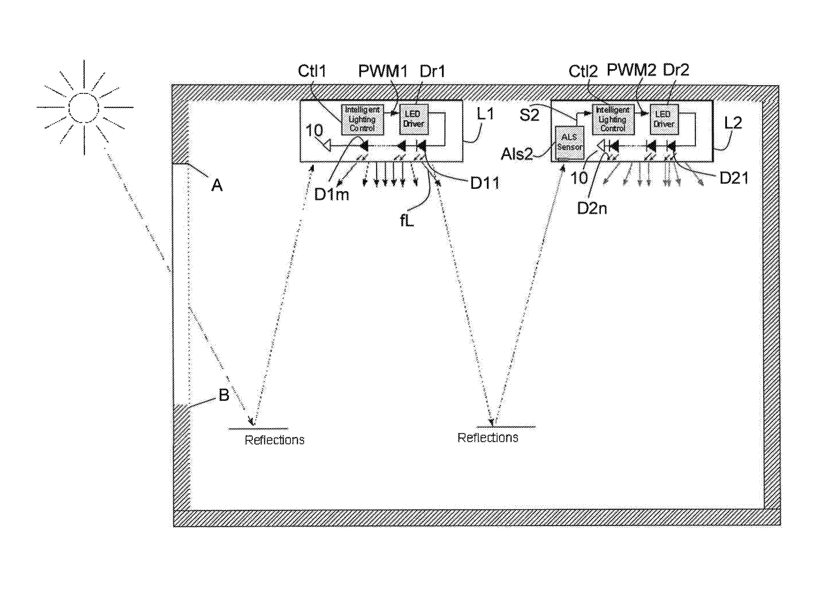
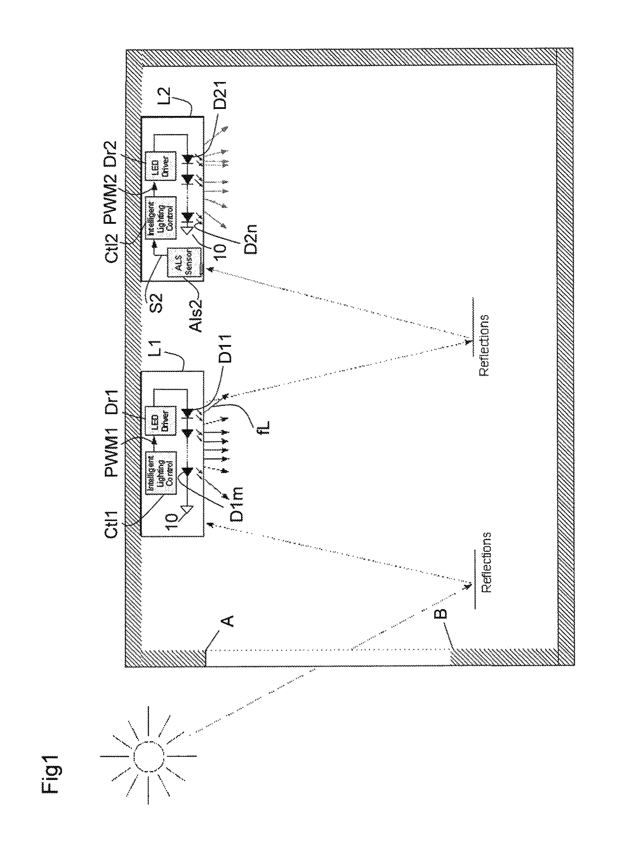
[0056]FIG. 1 shows an exemplary embodiment of the electronic lighting arrangement according to the proposed teaching. A first light source L1 and a second light source L2 are arranged in one room. This room has a window extending between points A and B. The first light source L1 comprises a first control unit Ctl1 and a first driver circuit Dr1. The first light source L1 further has a number m of LEDs D11, D12, . . . , D1m connected in series to the first driver circuit DR1.

[0057]The first control unit Ctl1 provides a first driving signal PWM1 to the first driver circuit Dr1. The first driver signal PWM1 is a pulse width modulated signal having a first frequency f1. The first driver circuit Dr1 drives the connected LEDs D11, . . . , D1m using the first driving signal PWM1. Thereby, LEDs D11, . . . , D1m are connected in series to each other, the first LED D11 being connected to an output of the first driver circuit Dr1. The LEDs D11, . . . , D1m are referred to a reference potential...


PUM


Abstract

In one embodiment, an electronic lighting system comprises a first light source (L1) adapted to emit light with a first brightness as a function of a first driving signal (PWM1) having a first frequency (f1), at least one second light source (L2) having a main light sensor (Als2) for providing an brightness of light surrounding the second light source (L2), wherein the first light source (L1) is arranged in visual connection with the at least one second light source (L2). Thereby, the second light source (L2) is prepared to emit light with a second brightness as a function of a second driving signal (PWM2) with a second frequency (f2), the second frequency (f2) of the second driving signal (PWM2) being adjusted to a light frequency (fL) of the light emitted by the first light source (L1), the light frequency (fL) being detected by means of the main light sensor (Als2). Furthermore, a method for lighting synchronization is described.

Description

[0001]The application refers to an electronic lighting system and to a method for lighting synchronization.BACKGROUND OF THE INVENTION[0002]Light-emitting diodes, LEDs, are used more and more in the field of architectural lighting. One of their main advantages is that LEDs can be dimmed precisely and efficiently according to various needs. By this, light colour and light brightness, for instance, can be adjusted, also taking into account ambient light conditions.[0003]The present application refers to light sources based on LEDs which are operated by constant current sources driven with a pulse-width-modulated signal.[0004]As soon as more than one light source are mounted in a single room, each light source is driven with a slightly different frequency and / or phase. The use of various frequencies in various lights leads to a slow overall variation of the phase relationship between the frequencies, which causes sub-harmonics or beat frequencies. These beat frequencies have an adverse...

Claims


Application Information

Patent Timeline
Patent Type & Authority Patents(United States)
IPC IPC(8): H05B33/08H05B37/02H05B44/00
CPCH05B33/0851H05B33/0815H05B37/0272H05B45/44H05B47/11Y02B20/40H05B45/325H05B45/12
Inventor SCHOEGLER, WERNERPAURITSCH, MANFRED
Owner AMS AG
Why Eureka
Try Eureka