Endoscope comprising a system with multiple cameras for use in minimal-invasive surgery

a multi-camera system and endoscope technology, applied in the field of endoscopes with multi-camera systems, can solve problems such as inability to use these cameras

Active Publication Date: 2016-04-12
E SYS MEDICAL GMBH +1
View PDF40 Cites 196 Cited by
  • Summary
  • Abstract
  • Description
  • Claims
  • Application Information

AI Technical Summary

Benefits of technology

[0023]The present invention has the advantage that by means of providing and simultaneously using 2 imaging systems, an at least 2D overview camera and a 3D detail camera, which are inserted into the body of a patient via a single trocar (also combination trocar), it is possible to generate an at least 2D overview image with a high object field angle (wide angle of typically >90°) and a 3D detail image with a general object field angle of up to 70°. As a result, it is possible to represent the immediate area of operation and its surrounding area during an entire minimally invasive surgery, such as laparoscopic surgery. In this way, it is possible to represent all surgical instruments simultaneously even if due to their varying positions and the position of the camera or the endoscope, as well as the object field angle (FoV “field of view”), they are outside of the surgical field of view of both imaging devices at the distal end of the endoscope, because the additional imaging device can also capture instruments which are outside of the surgical field of view of both imaging devices. For example, this can be the case when a surgical instrument is temporarily not needed and “deposited”. In most cases, such “depositing” takes place outside of the immediate surgical procedure and outside of the surgical field of view so that the instruments are not in the way during surgery. According to the invention, such “deposited” surgical elements are captured by the invention-based 2D overview camera and are therefore constantly under visual control of the surgeon or his assistant. Since the additional imaging device designed as a 2D overview camera and the imaging device designed as 3D detail camera are arranged respectively on an endoscope, for example, in the form of 2 image sensors, the surgeon has no problem to watch the picture recordings of the 2D overview camera and the 3D detail camera via a mutual or separate monitor. For the surgeon it is easy to coordinate the images because the monitoring area of the 2D overview camera, which possibly can comprise a 3D lens, encompasses the monitoring area of the 2D detail camera or is larger than the object field angle of the 3D detail camera. In this regard, it should be mentioned that an arrangement of 2 separate cameras, which are positioned completely independent and have an overlapping monitoring area not attached to the endoscope, would result in unfavorable coordination for the surgeon, possibly causing him to become “seasick” because of the two completely independent cameras. This problem is solved in a simple manner by means of the invention-based endoscope with the 2D overview camera and the adjusted 3D detail camera.
[0018]FIG. 3 is a schematic partial view of a further, preferred embodiment of a 3D detail camera which can be implemented by means of a reduced number of the mechanical control members arranged at an invention-based endoscope.
[0014]In one embodiment, the additional image sensor comprises a wide-angle lens which is located near the distal end of the trocar when pivoted. In another embodiment, the two imaging devices are arranged at the distal end of the main support device, respectively, in such a manner that they can be rotated about a rotation axis, wherein the rotation axes are aligned in a plane parallel to one another. In a further embodiment, the additional support device is located between the trocar and the main support device, especially resting directly at the main support device, wherein in particular the main support device and the additional support device have a cylindrical design. In another embodiment, each of the imaging devices is arranged in such a way that it can be tilted by means of joints about the rotation axis, as well as about a further rotation axis, in orthogonal direction toward the longitudinal extension of the support device, wherein the rotary movements about the rotation axes and the rotation axes are decoupled independently of one another.
[0014]In one embodiment, the additional image sensor comprises a wide-angle lens which is located near the distal end of the trocar when pivoted. In another embodiment, the two imaging devices are arranged at the distal end of the main support device, respectively, in such a manner that they can be rotated about a rotation axis, wherein the rotation axes are aligned in a plane parallel to one another. In a further embodiment, the additional support device is located between the trocar and the main support device, especially resting directly at the main support device, wherein in particular the main support device and the additional support device have a cylindrical design. In another embodiment, each of the imaging devices is arranged in such a way that it can be tilted by means of joints about the rotation axis, as well as about a further rotation axis, in orthogonal direction toward the longitudinal extension of the support device, wherein the rotary movements about the rotation axes and the rotation axes are decoupled independently of one another.
[0014]In one embodiment, the additional image sensor comprises a wide-angle lens which is located near the distal end of the trocar when pivoted. In another embodiment, the two imaging devices are arranged at the distal end of the main support device, respectively, in such a manner that they can be rotated about a rotation axis, wherein the rotation axes are aligned in a plane parallel to one another. In a further embodiment, the additional support device is located between the trocar and the main support device, especially resting directly at the main support device, wherein in particular the main support device and the additional support device have a cylindrical design. In another embodiment, each of the imaging devices is arranged in such a way that it can be tilted by means of joints about the rotation axis, as well as about a further rotation axis, in orthogonal direction toward the longitudinal extension of the support device, wherein the rotary movements about the rotation axes and the rotation axes are decoupled independently of one another.
[0014]In one embodiment, the additional image sensor comprises a wide-angle lens which is located near the distal end of the trocar when pivoted. In another embodiment, the two imaging devices are arranged at the distal end of the main support device, respectively, in such a manner that they can be rotated about a rotation axis, wherein the rotation axes are aligned in a plane parallel to one another. In a further embodiment, the additional support device is located between the trocar and the main support device, especially resting directly at the main support device, wherein in particular the main support device and the additional support device have a cylindrical design. In another embodiment, each of the imaging devices is arranged in such a way that it can be tilted by means of joints about the rotation axis, as well as about a further rotation axis, in orthogonal direction toward the longitudinal extension of the support device, wherein the rotary movements about the rotation axes and the rotation axes are decoupled independently of one another.
[0029]Consequently, according to the present invention, it is possible when using only one trocar that the 3D detail camera can be moved in 4 degrees of freedom independent of the 2D overview camera. The 2D overview camera and the 3D detail camera, in turn, are connected with one another in 2 degrees of freedom, which represent the movements in x and y direction (pivot movement of the trocar) about the insertion point of the trocar into the body.
[0010]In another aspect, the invention provides a surgical robot system having at least one robotic arm on which at least one surgical instrument and / or one endoscope can be arranged, which comprises
[0011]a main support device that basically extends over the entire length of the endoscope from the outside to the interior of the body, and which comprises at its distal end at least one lighting unit and two imaging devices, wherein each of the imaging devices is basically arranged in such a way that it can be rotated to the outside on the same level as the main support device,
[0007]a trocar, by means of which the endoscope can enter the body, and
[0013]an additional support device, which is provided at the trocar and / or the main support device, wherein the additional support device comprises at its distal end an additional imaging device, which can be rotated from the additional support device to the outside and wherein the additional imaging device comprises an additional lighting unit and at least an additional image sensor, which comprises a monitoring area, which encompasses the two monitoring areas of the imaging devices of the main support device, wherein provision has been made for an image processing unit, which is connected with the two imaging devices and the additional imaging device, and a visualization unit, which represents 2D image data and / or 3D image data of the imaging devices and / or the additional imaging device.
[0033]wherein provision has been made for an image processing unit, which is connected with the two imaging devices and the additional imaging device, and a visualization unit, which represents 2D image data and / or 3D image data of the imaging devices and / or the additional imaging device.
[0034]In particular, the invention-based surgical robot system has the advantage that depending on the needs the image data for the surgeon can be represented as 2D image data and / or 3D image data, i.e., the image data of the overview camera can be coupled with the image data of the 3D detail data by means of the image processing unit, providing the surgeon with a considerably improved overview through a single frame sequence on the visualization unit.
[0035]In particular, it is advantageous that the additional image sensor comprises a wide-angle lens which is located near the distal end of the trocar when pivoted.
[0015]The present invention is explained in more detail by means of the enclosed exemplary figures. It is shown:
[0036]The sub-claims show further advantageous embodiments of the invention. Accordingly, the entire disclosure of the present invention refers to the two camera systems, as well as the endoscope encompassing the two camera systems.
[0037]In minimally invasive surgery, such as laparoscopic surgery, the body of a patient is accessed via a trocar (usually through the abdominal wall or into the thorax). A surgical instrument or a camera or endoscope can be inserted into the body through such a trocar. As mentioned before, according to the invention, via a trocar two cameras are simultaneously inserted. A surgical procedure usually involves 2 to 4 surgical instruments and at least one camera. Therefore, 3 to 5 trocars are required for such a surgical procedure.

Problems solved by technology

The camera systems or endoscopes described in prior art have the disadvantage that even if two cameras are provided for taking images of the area of operation, it is not possible for these cameras to represent simultaneously in each constellation all surgical instruments due to the varying positions of the surgical instruments and the position of the endoscope near the surgical procedure, as well as the object field angle (FoV “field of view”), wherein merely the immediate area of the surgical procedure is represented.

Method used


Image

  • Endoscope comprising a system with multiple cameras for use in minimal-invasive surgery
  • Endoscope comprising a system with multiple cameras for use in minimal-invasive surgery
  • Endoscope comprising a system with multiple cameras for use in minimal-invasive surgery

Examples


Embodiment Construction

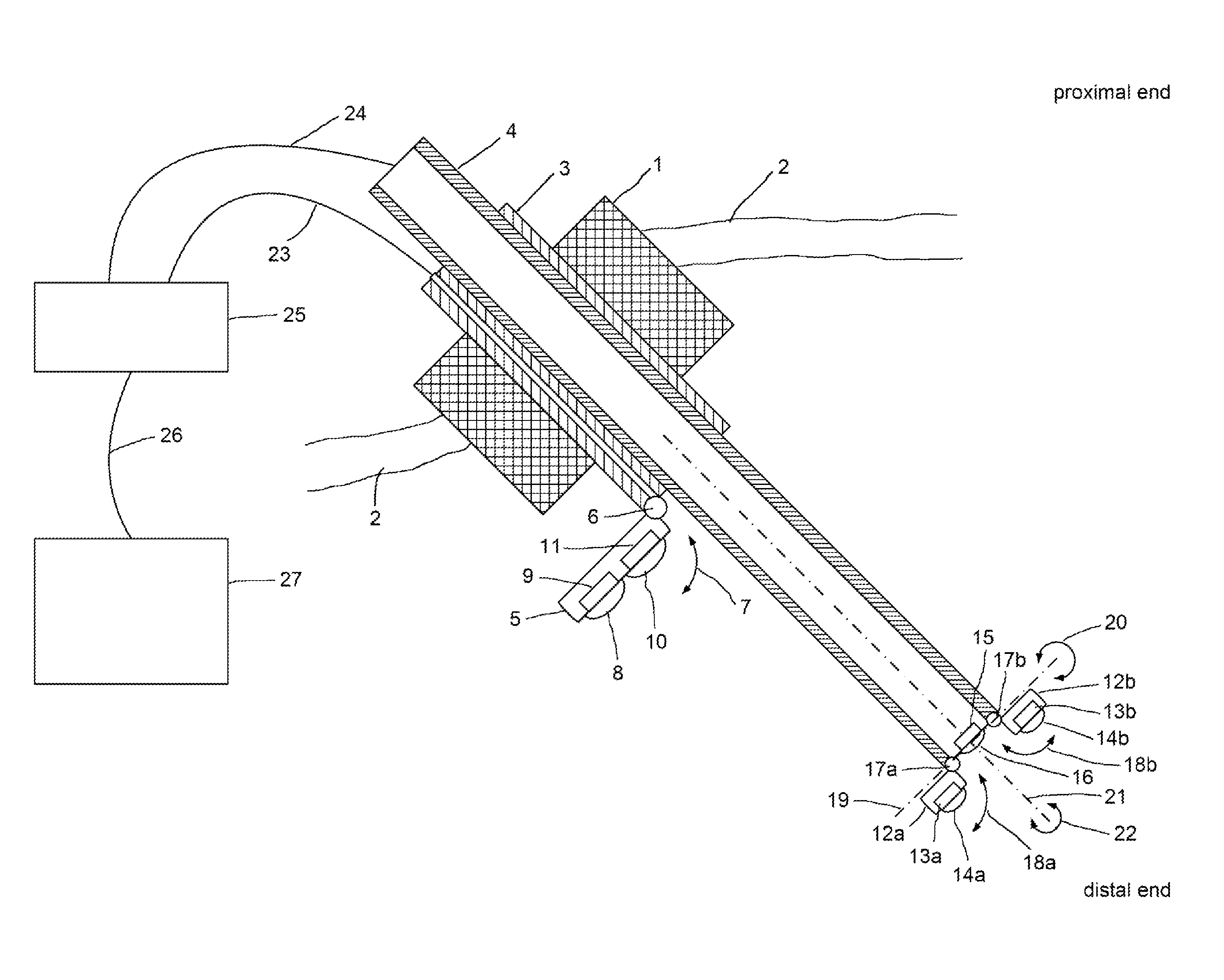
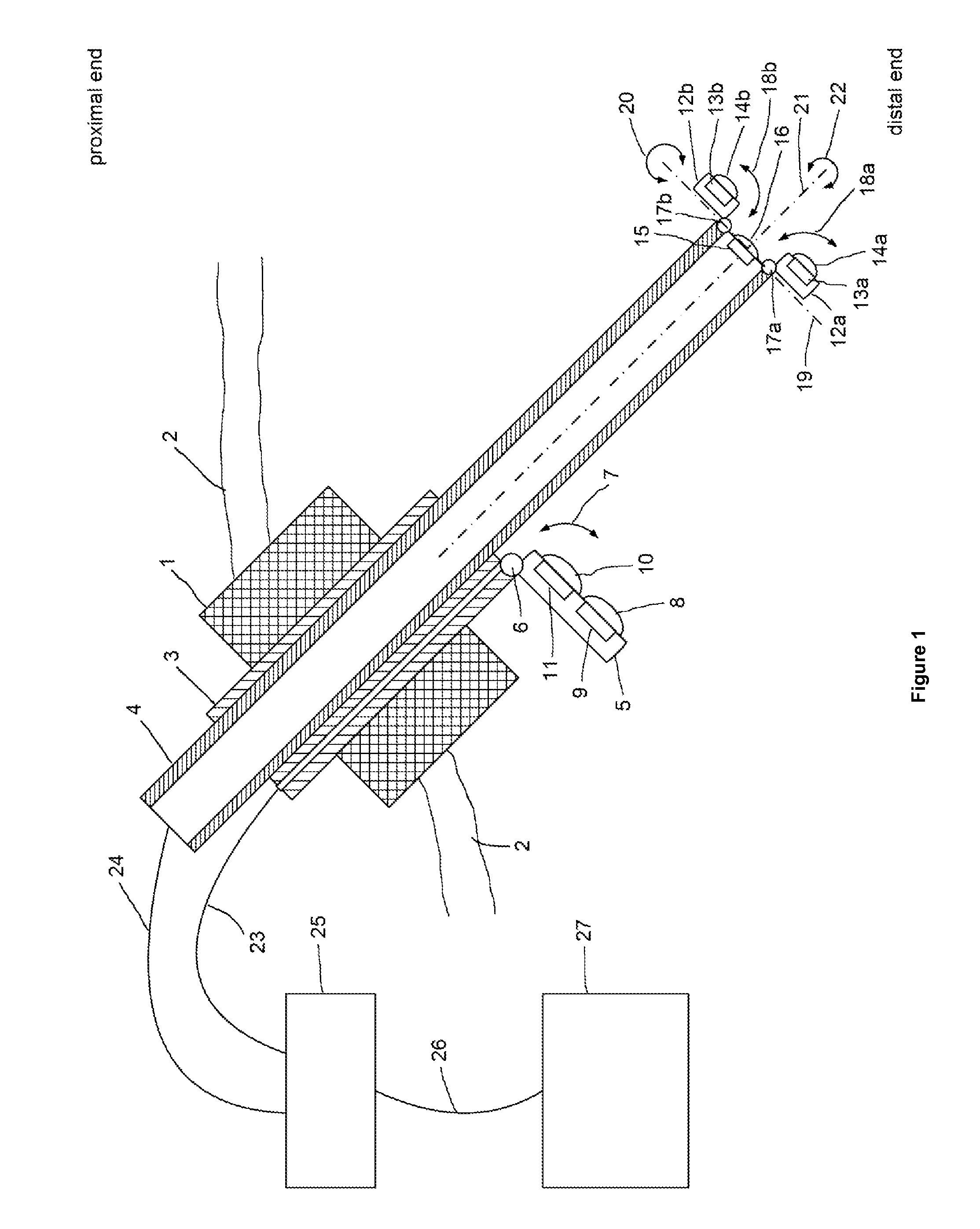
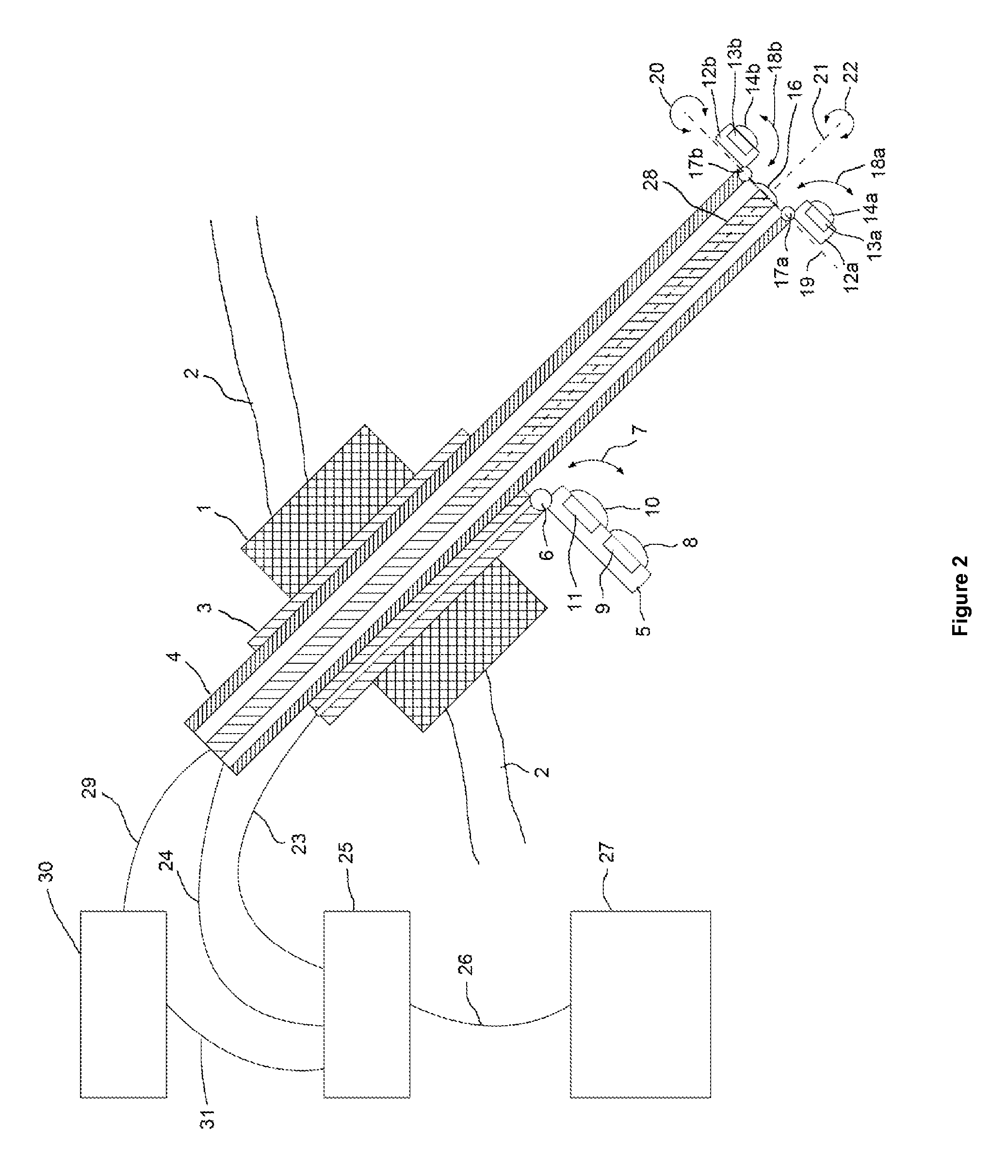
[0020]The invention is therefore based on the objective of providing an improved visualization system for minimally invasive surgeries, such as laparoscopic surgeries, which allows the surgeon to coordinate the instruments in a simple manner using a single trocar to access the body without having to use an additional trocar to access the body. According to the present invention, this objective is achieved by means of the endoscopes and surgical robot systems disclosed herein.

[0021]The present invention provides an endoscope with a multi-camera system for use in minimally invasive surgery, such as laparoscopy.

[0022]A first object of the present invention concerns an endoscope for minimally invasive surgery, especially for use within a surgical robot system, which basically extends over the entire length of the endoscope from the outside to the interior of the body, and which comprises at its distal end at least one lighting unit and two imaging devices, wherein each of the imaging de...


PUM


Abstract

The present invention concerns an endoscope for minimally invasive surgery, especially for use within a surgical robotic system, which comprises a main support device (4), which basically extends over the entire length of the endoscope from the outside to the interior of the body, and which comprises at its distal end at least one illumination unit (15, 16) and two imaging devices (12a, 13a, 14a, 12b, 13b, 14b; 12c), wherein each of the imaging devices (12a, 13a, 14a, 12b, 13b, 14b; 12c) is basically arranged in such a way that it can be rotated to the outside on the same level as the main support device (4), a trocar (1), by means of which the endoscope can enter the body, and an additional support device (3), which is provided at the trocar (1) and / or the main support device (4), wherein the additional support device (3) comprises at its distal end an additional imaging device (8, 9, 10, 11), which can be rotated from the additional support device (3) to the outside and wherein the additional imaging device (7, 8, 9, 10) comprises an additional illumination unit (10, 11) and at least an additional image sensor (8, 9), which comprises a monitoring area, which encompasses the two monitoring areas of the imaging devices (12a, 13a, 14a, 12b, 13b, 14b; 12c) of the main support device (4).

Description

CROSS REFERENCE[0001]This application claims priority to German Patent Application Serial No. DE 10 2012 025 102.5, filed Dec. 20, 2012, incorporated by reference herein in its entirety.FIELD OF THE INVENTION[0002]The present invention concerns an endoscope with a multi-camera system for use in minimally invasive surgeries and a respective surgical robot, especially for use in minimally invasive surgery, such as laparoscopy.BACKGROUND[0003]Minimally invasive surgeries, such as laparoscopic operations, are performed with the use of surgical instruments, for example, forceps, cutting and sewing tools, which are inserted into the body of a patient via one or several trocars. Usually, two to four, in most cases three surgical instruments are used. In addition to these instruments, it is required that a visualization unit is available which allows the surgeon to observe the area of operation. Such a visualization unit always comprises a camera or an endoscope, which are also inserted int...

Claims


Application Information

Patent Timeline
Patent Type & Authority Patents(United States)
IPC IPC(8): A61B1/04A61B1/00A61B1/313A61B1/32A61B1/05A61B1/06A61B17/34
CPCA61B1/00064A61B1/00183A61B1/313A61B1/32A61B1/05A61B90/30A61B17/3421A61B2090/371A61B34/30A61B1/00149A61B1/00193A61B1/0661
Inventor VON GRUNBERG, HUBERTUSSEEBER, MARCELSTOLZENBURG, JENS-UWE
Owner E SYS MEDICAL GMBH
Why Eureka
Try Eureka