Apparatus and method for automatic inspection of through-holes of a component

a technology of automatic inspection and through-holes, which is applied in the field of automatic inspection of through-holes of components, can solve the problems of difficult identification and analysis of through-holes using standard image processing techniques, and achieve the effects of increasing contrast or sensitivity, time-consuming and laborious, and small dimensions

Active Publication Date: 2016-04-12
SIEMENS ENERGY GLOBAL GMBH & CO KG
View PDF27 Cites 15 Cited by
  • Summary
  • Abstract
  • Description
  • Claims
  • Application Information

AI Technical Summary

Benefits of technology

[0010]The underlying idea of the present invention is to provide an automatic evaluation of a thermographic image by correlating the thermographic to a digital image obtained from geometrical data of the component. Using the digital image of the component, a digital image mask is computed based on a determination of the positions of through-holes in the digital image. The thermographic image is fitted on to the digital image and the regions corresponding to through-holes in the thermographic image are extracted using the computed digital image mask. A blockage or irregularity in the through-hole is determined by evaluating this masked thermographic image. One of problems with the existing state of the art is that thermographic images have high noise component and hence it is difficult to identify and analyze through-holes using standard image processing techniques. This problem is solved herein by the use of the above-mentioned digital image mask, to extract the through-holes in the thermographic image. The above method is completely automatic and is considered to be advantageous over the subjective evaluation of thermographic images in the mentioned state of the art.
[0014]In one embodiment, the step of fitting comprises fitting the thermographic image directly on a three-dimensional digital image of the component. This eliminates the additional step of creating a two-dimensional image for fit with the thermographic image. This embodiment is particularly advantageous if the clamping or positioning of the component is reproducible, which allows the test set up to be calibrated or measured just once.
[0016]In a further embodiment, a blockage or irregularity in a particular through-hole is determined by comparing a temperature of that through-hole as indicated in the masked thermographic image to a reference temperature value. In principle, during thermographic imaging when a heated medium is forced into the through-holes, the through-holes act as black-body cavity radiators and as such, they approach behaving as idealized sources of radiation. A blockage in the through hole thus reduces the temperature of the through-hole, which is visible in the thermographic image.
[0020]When both a heat-up cycle and a cool-down cycle are analyzed in tandem, is possible to obtain increased contrast or sensitivity in the thermographic image, which can be used to detect partial blockages or other minor irregularities in the through-holes.
[0021]In an exemplary embodiment, said component is a turbomachine blade or vane, and wherein said through-holes are cooling holes. Cooling holes in turbine blades or vanes have extremely small dimensions, which makes a manual evaluation of thermographic images rather time consuming and labor intensive. The use of the present invention herein reduces the testing time and eliminates the need of trained personnel for this purpose.

Problems solved by technology

One of problems with the existing state of the art is that thermographic images have high noise component and hence it is difficult to identify and analyze through-holes using standard image processing techniques.

Method used


Image

  • Apparatus and method for automatic inspection of through-holes of a component
  • Apparatus and method for automatic inspection of through-holes of a component
  • Apparatus and method for automatic inspection of through-holes of a component

Examples


Embodiment Construction

[0031]The embodiments described below illustrate the use of the present invention for automatic inspection of cooling holes of a turbomachine blade or vane of the type mentioned above. However, the present invention may be used for several other industrial applications that involve automatic inspection of through-holes of a component.

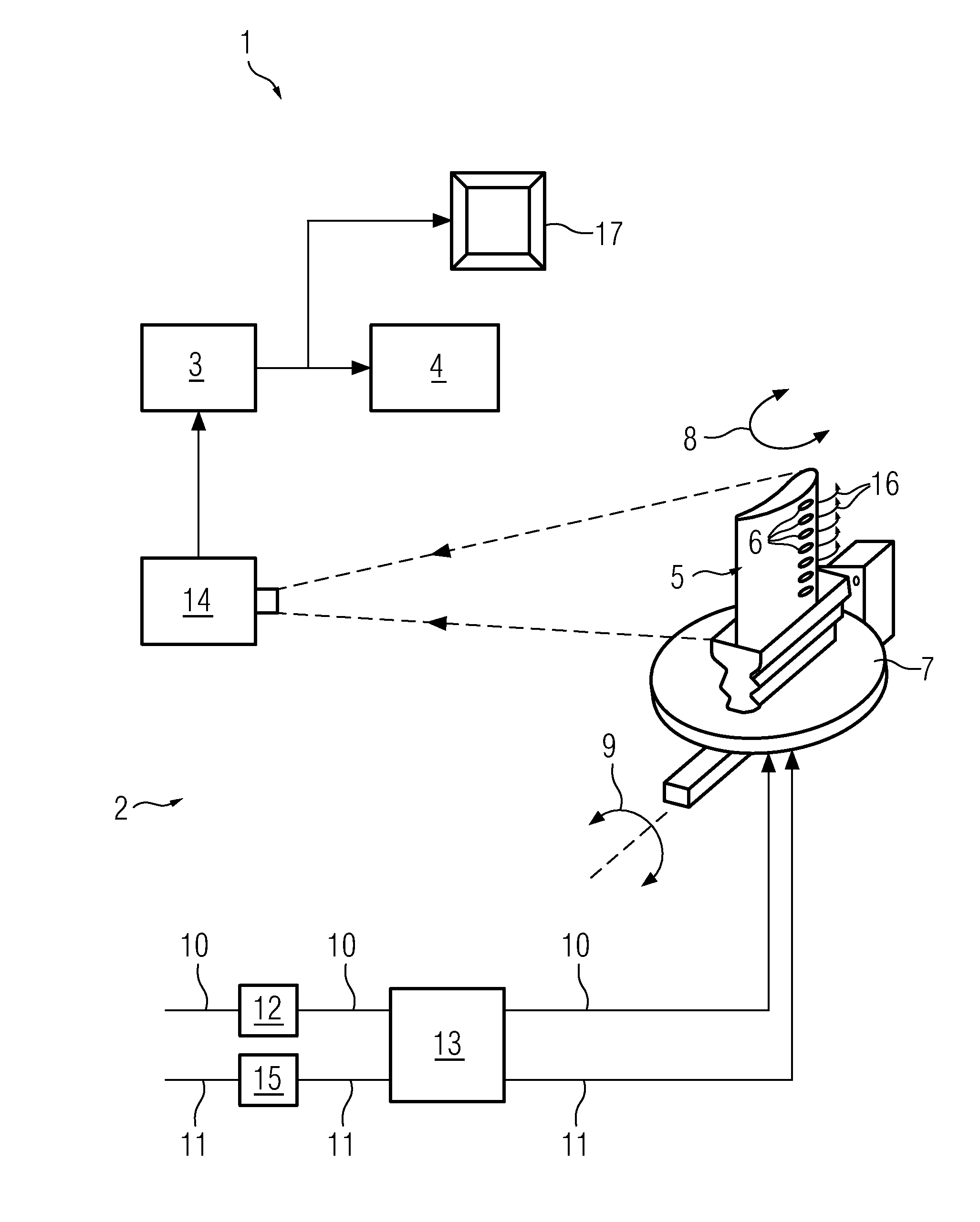
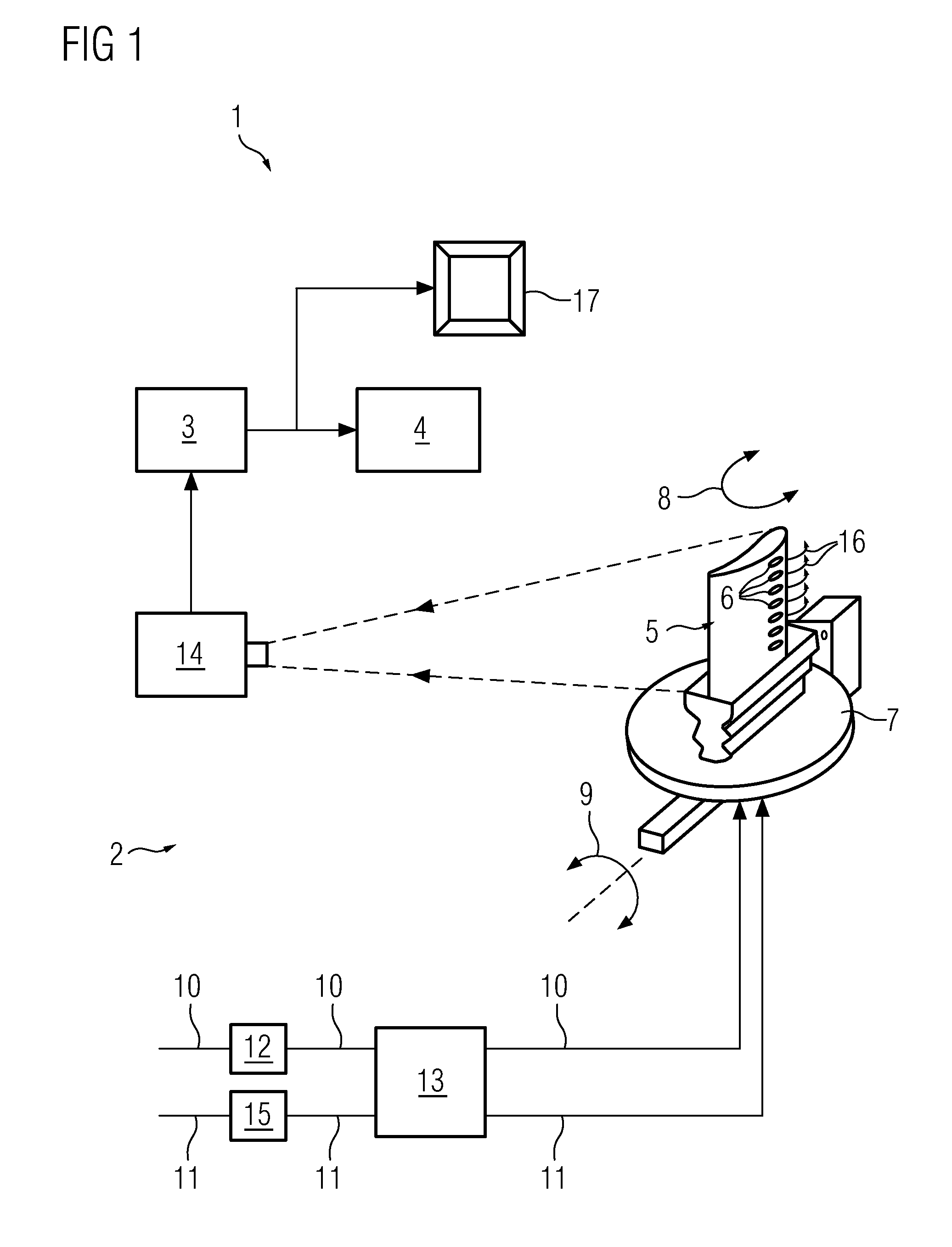
[0032]Referring to FIG. 1 is illustrated an apparatus 1 for inspecting through-holes 6 formed in a component 5. In this example, the component 5 is a turbine blade or vane, and the through-holes 6 include cooling holes. The apparatus 1 broadly includes an imaging module 2 for generating a thermographic image of the blade or vane 5, an image processing module 3 for extracting regions corresponding to cooling holes from the thermographic image, and an analysis module 4 for evaluating this extracted portion of the thermographic image to determine the presence of a blockage or irregularity in one or more of the cooling holes.

[0033]In the illustrated embodim...


PUM

PropertyMeasurementUnit
degrees of freedomaaaaaaaaaa
temperatureaaaaaaaaaa

Abstract

An apparatus and a method for automatic inspection of through-holes of a component is provided. The proposed apparatus includes an imaging module, an image processing module and an analysis module. The imaging module generates a thermographic image of the component by passing a medium through the through-holes and capturing infra-red radiation emitted from the component while the medium is flowing through the through-holes. The image processing module fits the thermographic image on a digital image obtained from geometrical data of the component. The image processing module is further masks the fitted thermographic image using a digital image mask to extract regions corresponding to through-holes in the thermographic image. The digital image mask is computed based on a determination of positions of through-holes on the digital image. The analysis module evaluates the masked thermographic image to determine an irregularity or blockage in one or more of the through-holes.

Description

CROSS REFERENCE TO RELATED APPLICATIONS[0001]This application is the US National Stage of International Application No. PCT / EP2011 / 065906, filed Sep. 14, 2011 and claims the benefit thereof. The International Application claims the benefits of European Patent Office application No. 10176521.2 EP filed Sep. 14, 2010. All of the applications are incorporated by reference herein in their entirety.FIELD OF INVENTION[0002]The present invention relates to inspection of through-holes of a component, and in particular, to a method and apparatus for automatic inspection of through-holes of a component using thermography.BACKGROUND OF INVENTION[0003]In several industrial applications, components having through-holes need to be inspected for proper functioning of the component. One such example is a turbomachine blade or vane. Turbomachines, particularly gas turbines, have vanes and blades that contain channels or through-holes which lead from an exterior surface of the blade or vane to a holl...

Claims


Application Information

Patent Timeline
Patent Type & Authority Patents(United States)
IPC IPC(8): G06K9/00G01N21/88G01N25/72G06T7/00
CPCG01N21/8851G01N25/72G06T7/0004G06T7/0081G06T7/0097G06T2207/10048G06T2207/30164G06T7/11G06T7/174
Inventor JAHNKE, RONNYSCZEPUREK, TRISTAN
Owner SIEMENS ENERGY GLOBAL GMBH & CO KG
Why Eureka
Try Eureka