Reconfigurable fiber optic adapter

a fiber optic adapter and reconfigurable technology, applied in the field of electrical connector technology, can solve the problems of wasting time and labor in the mounting procedure, difficult and complicated to affix the optical fibers to the plug member of the optical fiber connector with epoxy resin, and difficulty in removing the optical fibers, so as to save installation time and labor, and high structural stability

Active Publication Date: 2016-04-12
CORNING OPTICAL COMM LLC
View PDF38 Cites 48 Cited by
  • Summary
  • Abstract
  • Description
  • Claims
  • Application Information

AI Technical Summary

Benefits of technology

[0011]To achieve this and other objects of the present invention, a reconfigurable fiber optic adapter of the invention is adapted for connecting male and female optical fiber connectors together, comprising a housing and two mating-connection control members. The housing comprises a base portion, two mating connection portions located at opposing front and rear sides of the base portion, a passage extending through the two mating connection portions and the base portion, two plug mouths respectively formed in the mating connection portions in communication between the passage and the atmosphere, a first keyway located in an inner top wall inside the passage and extending from one plug mouth to the other, a second keyway located in an opposing inner bottom wall inside the passage and extending from one plug mouth to a middle part in the base portion, two recesses located in opposing top and bottom sides of one mating connection portion, two mounting groove units bilaterally located in each recess, and two pairs of hook holes located in the opposing top and bottom sides of the mating connection portion carrying the recesses. The two mating-connection control members are selectively and exchangeably mounted in the mounting groove units in the recesses for controlling the insertion direction of a mating optical fiber connector. Each mating-connection control member comprises a base panel inserted into one recess of the housing, two hook rods extended from the base panel and hooked in respective hook holes in the housing, and an Off key or On key located on a middle part of a bottom side of the base panel. The Off key of one mating-connection control member and the On key of the other mating-connection control member have different heights so that the Off key projects into the sliding path of one of the first keyway and second keyway, and the On key is kept in flush with the bottom wall of the other of the first keyway and second keyway. Thus, the invention allows the optical fiber connector at the end-user side to be conveniently connected to the optical fiber connector at the telecommunication-operator side without reconfigurating the connection between the fiber optic cable and the respective optical fiber connector, saving much installation time and labor and assuring a high level of structural stability.
[0012]Further, each hook rod of each mating-connection control member is terminated in a beveled guide face and then a stepped engagement portion. When inserting the base panel of each mating-connection control member into one respective recess of the housing, the beveled guide faces of the hook rods will be forced against a part of the respective mating connection portion to elastically deform the hook rods. At this time, the Off key is inserted into the sliding path of the first keyway or second keyway, the On key will be kept away from the sliding path of the first keyway or second keyway. After the base panel is pushed into position, the stepped engagement portions of the hook rods are respectively hooked in the respective hook holes in the housing to lock the respective mating-connection control members to the housing. After the two mating-connection control members are installed in the housing, the On key and the Off key face toward each other. Further, the two mating-connection control members are colored in different colors for easy identification of the Off key or On key.
[0013]Further, when the plug member of one optical fiber connector is inserted through one plug mouth of the housing into the passage, the On key is kept away from the sliding path of the first keyway or second keyway so that the directional key of the inserted optical fiber connector can pass over the On key into the deep inside of the passage and connected to the other mating optical fiber connector in the opposite side of the housing of the reconfigurable fiber optic adapter for transmitting an optical signal. By means of suspending the Off key in the sliding path in the first keyway, the directional key of the optical fiber connector will be stopped by the Off key from entering the passage, preventing installation of the optical fiber connector in the wrong direction.

Problems solved by technology

During this mounting procedure, it is difficult and complicated to affix the optical fibers to the plug member of the optical fiber connector with epoxy resin and to polish the ends of the optical fibers.
Further, this mounting procedure wastes much time and labor.

Method used


Image

  • Reconfigurable fiber optic adapter
  • Reconfigurable fiber optic adapter
  • Reconfigurable fiber optic adapter

Examples


Embodiment Construction

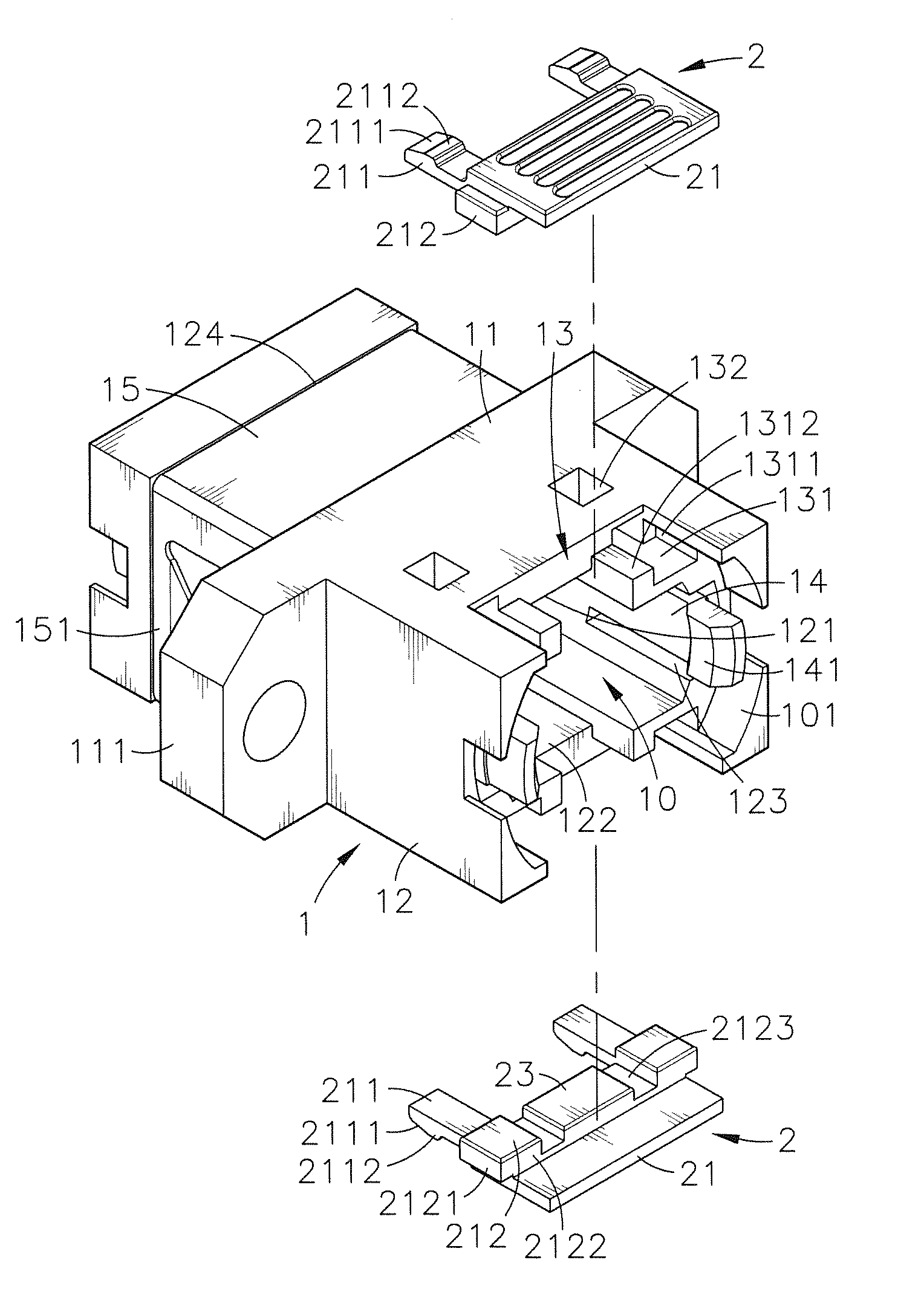
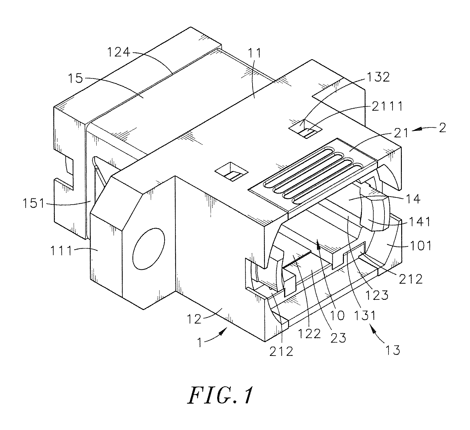
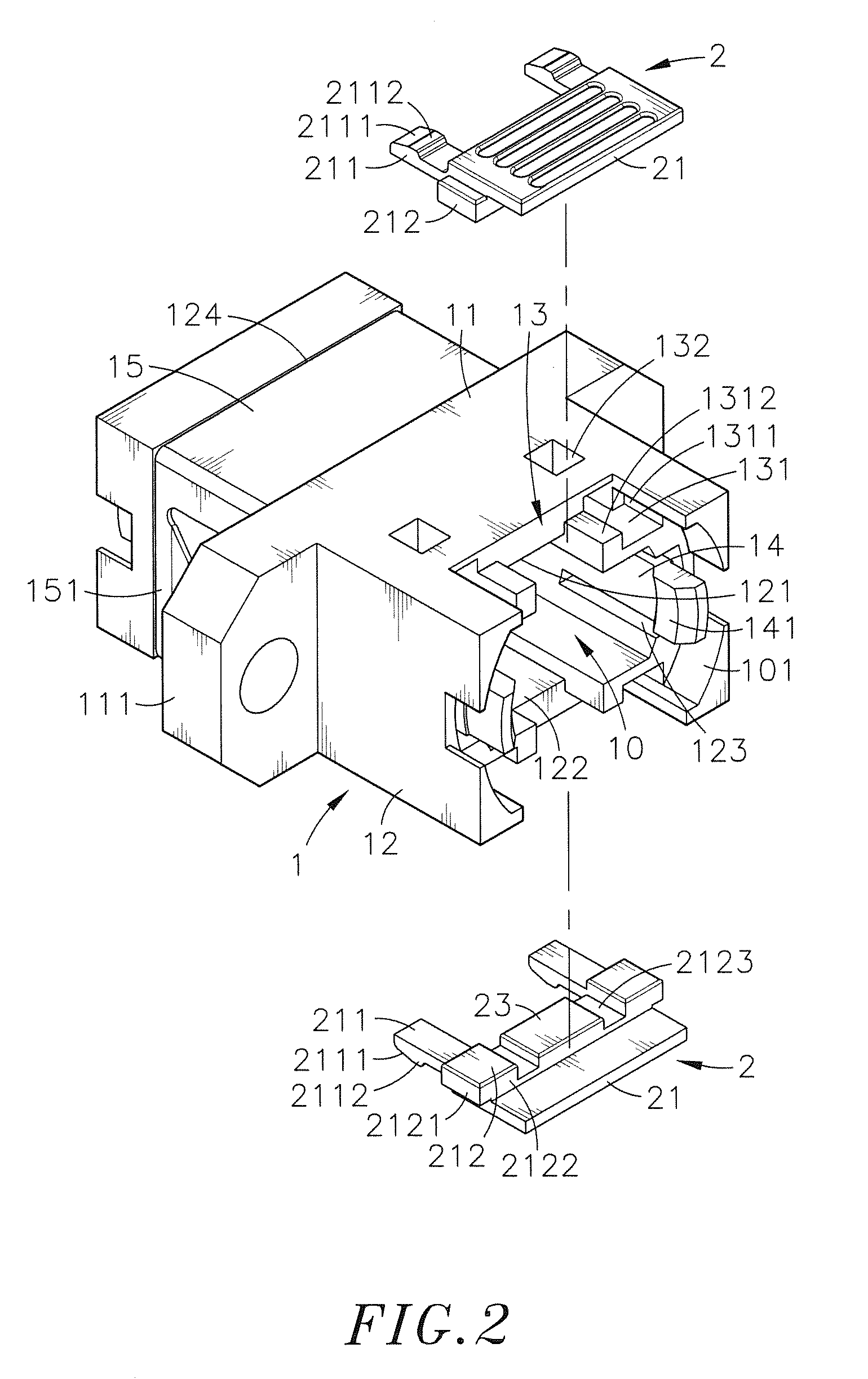
[0026]Referring to FIGS. 1-6, a reconfigurable fiber optic adapter in accordance with the present invention is shown. The reconfigurable fiber optic adapter comprises a housing 1, and two mating-connection control members 2.

[0027]The housing 1 comprises a base portion 11, two side flanges 111 symmetrically located at opposing left and right sides of the base portion 11, two mating connection portions 12 located at opposing front and rear sides of the base portion 11, a passage 10 extending through the two mating connection portions 12 and the base portion 11, two plug mouths 101 respectively formed in the mating connection portions 12 in communication between the passage 10 and the atmosphere, a first keyway 121 located in an inner top wall inside the passage 10 and extending from one plug mouth 101 (the plug mouth at the front side) to the other (the plug mouth at the rear side), a second keyway 122 located in an opposing inner bottom wall inside the passage 10 and extending from o...


PUM


Abstract

A reconfigurable fiber optic adapter for connecting male and female optical fiber connectors is disclosed to include a housing having two recessed located in opposing top and bottom sides of one end thereof and opposing first and second keyways located in opposing top and bottom sides of a optical fiber connector passage therein, and a first mating-connection control member with an On key and a second mating-connection control member with an OFF key selectively exchangeably mounted in the two recesses of the housing for controlling the insertion direction of a male optical fiber connector.

Description

[0001]This reference is based on Provisional Application Ser. No. 61 / 966,301, filed on Feb. 21, 2014.BACKGROUND OF THE INVENTION[0002]1. Field of the Invention[0003]The present invention relates to electrical connector technology and more particularly, to a reconfigurable fiber optic adapter, which allows position exchange between two mating-connection control members that are provided with an Off key or On key, controlling the insertion direction of a mating optical fiber connector.[0004]2. Description of the Related Art[0005]With rapid development of modern communications technology and the Internet, data centers and telecommunications providers are trying hard to provide relative equipment having the characteristics of high density, high transmission speed, high capacity and high intelligence. In order to meet the demands for faster data transmission speed, smaller footprint and lower energy consumption, the physical infrastructure of cabling system has been receiving more attent...

Claims


Application Information

Patent Timeline
Patent Type & Authority Patents(United States)
IPC IPC(8): G02B6/38
CPCG02B6/3831G02B6/3825G02B6/3885
Inventor LEE, WEI-CHENG
Owner CORNING OPTICAL COMM LLC
Why Eureka
Try Eureka