Parallel link mechanism, constant velocity universal joint, and link actuator
a technology of constant velocity universal joints and link actuators, applied in the field of parallel, can solve the problems of increasing the dimensions of the mechanism as a whole, the weight of the tool mounted on the travelling plate, and the bulkyness of the apparatus, so as to achieve easy construction, increase the sealing ability, and facilitate the effect of fixing
- Summary
- Abstract
- Description
- Claims
- Application Information
AI Technical Summary
Benefits of technology
Problems solved by technology
Method used
Image
Examples
first embodiment
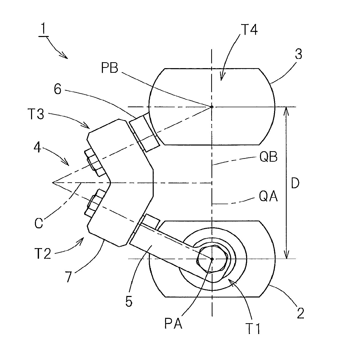
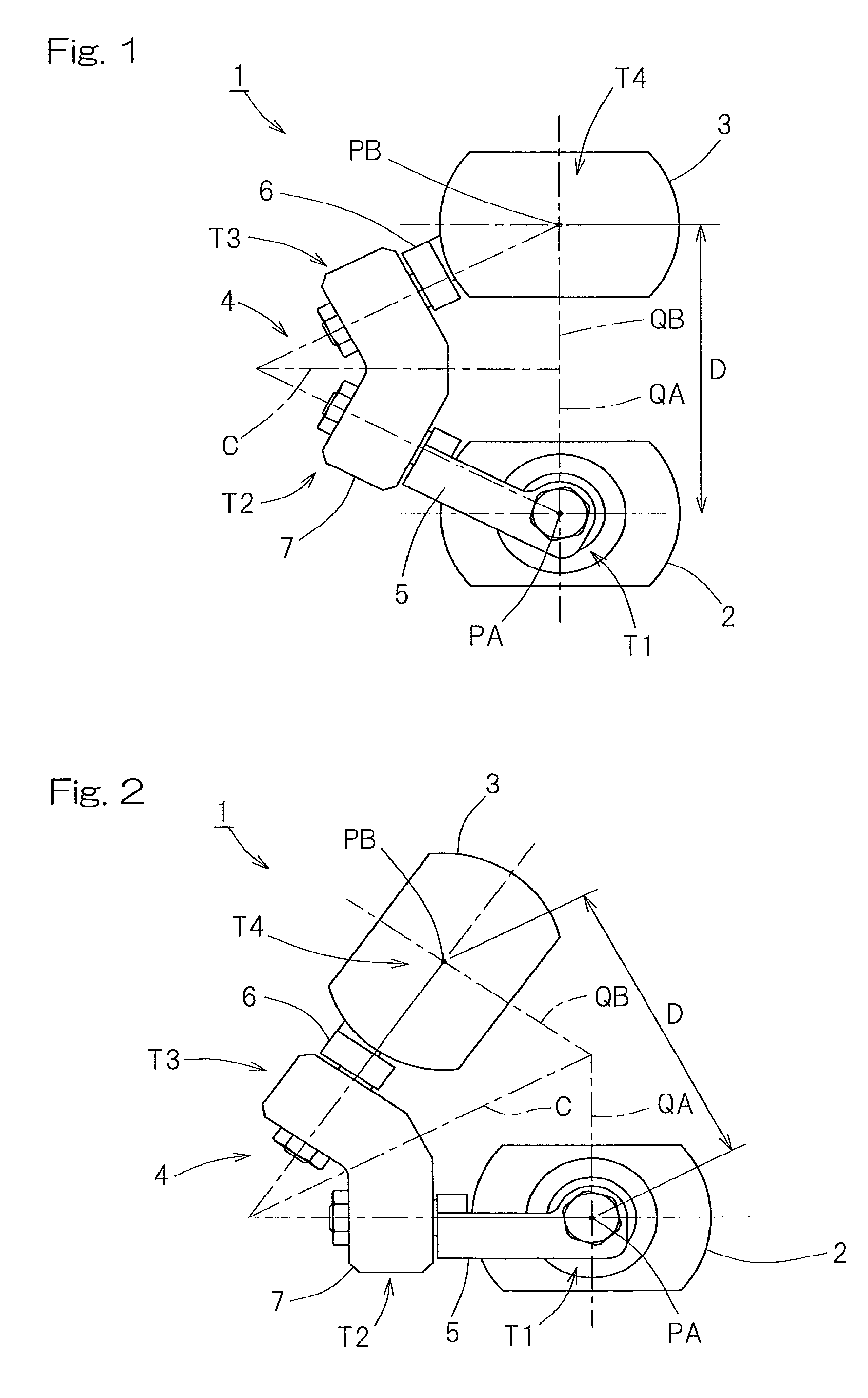
[0057]A parallel link mechanism according to the present invention will be described with reference to FIG. 1 to FIG. 7. FIG. 1 and FIG. 2 are front views respectively showing different states of the parallel link mechanism 1. The parallel link mechanism 1 is of a type in which a distal end side link hub 3 is connected to a proximal end side link hub 2 via three link mechanisms 4 in a position-changeable fashion. In FIG. 1 and FIG. 2, only one link mechanism 4 is shown.
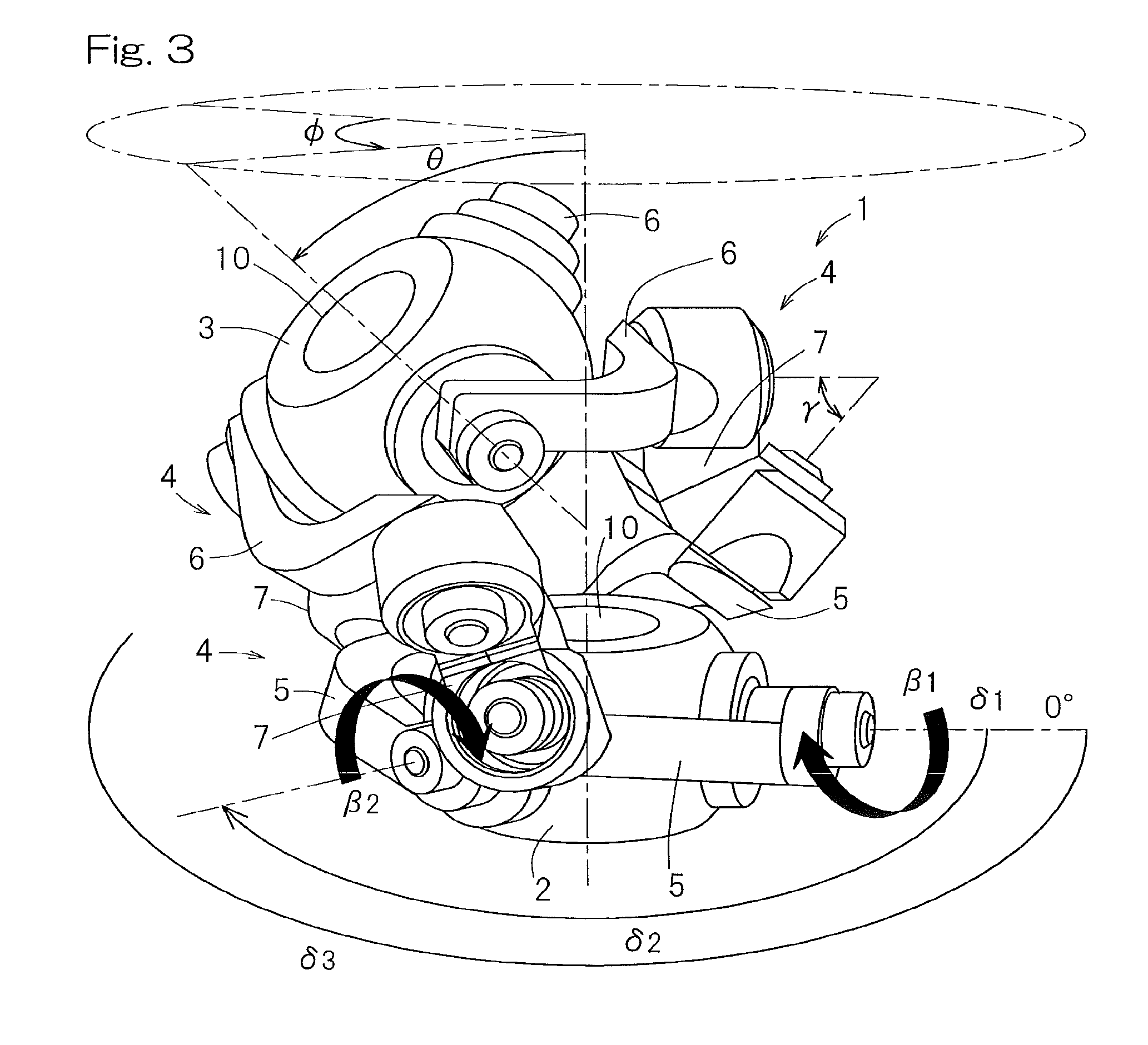
[0058]FIG. 3 is a perspective view showing a three-dimensional representation of the parallel link mechanism 1. Each link mechanism 4 includes a proximal side end link member 5, a distal side end link member 6, and an intermediate link member 7, and forms a trinodal link mechanism including four revolute pairs. Each of the proximal side and distal side end link members 5 and 6 has an L-shape. The proximal end portion of the proximal side end link member 5 is pivotably connected to the proximal end side link hub 2, and...
second embodiment
[0092]FIGS. 8 to 11 show the present invention, in which a different type of the parallel link mechanism is used. This parallel link mechanism 1 has the bearings 12 (FIG. 9), of an outer ring rotation type, which rotatably support each end link member 5 relative to the proximal end side link hub 2 and each end link member 6 relative to the distal end side link hub 3. Now, description is made with respect to the revolute pair section T1 between the proximal end side link hub 2 and the proximal side end link member 5 as an example. As shown in FIG. 9, the proximal end side link hub 2 has shaft portions 35 formed at three circumferential locations thereof. On the outer periphery of each shaft portion 35, the end link member 5 is rotatably supported via the two bearings 12 juxtaposed to each other. The two bearings 12 are provided in a communication hole 34 formed in the end link member 5, and are fastened and fixed, via a spacer member 36, by means of a nut 37 threadedly engaged on a t...
third embodiment
[0106]FIG. 13 shows a constant velocity universal joint according to the present invention, which uses a parallel link mechanism. This constant velocity universal joint 61 is of a type in which an input shaft 63 is mounted via a mounting plate 62 to the proximal end side link hub 2 of the parallel link mechanism 1 shown in FIG. 1 to FIG. 7 and an output shaft 65 is mounted via a mounting plate 64 to the distal end side link hub 3 thereof. The axes of the input shaft 63 and the output shaft 65 are respectively aligned with the central axis QA of the proximal end side link hub 2 and the central axis QB of the proximal end side link hub 3.
[0107]With respect to the parallel link mechanism 1, in a case where the angles and the lengths of the shaft members 13 (FIG. 5) in the proximal end side link hub 2 and the output side link hub 3 are identical with each other, the geometrical shapes of the proximal side end link member 5 and the distal side end link member 6 are identical with each ot...
PUM
 Abstract
Description
Claims
Application Information
 - R&D
- Intellectual Property
- Life Sciences
- Materials
- Tech Scout
- Unparalleled Data Quality
- Higher Quality Content
- 60% Fewer Hallucinations
Browse by: Latest US Patents, China's latest patents, Technical Efficacy Thesaurus, Application Domain, Technology Topic, Popular Technical Reports.
© 2025 PatSnap. All rights reserved.Legal|Privacy policy|Modern Slavery Act Transparency Statement|Sitemap|About US| Contact US: help@patsnap.com


