Process chamber incorporating an arrangement for injecting gaseous fluid thereinto

a technology of process chamber and gaseous fluid, which is applied in the direction of vehicle cleaning, vehicle cleaning, and drying machines with progressive movements, etc., can solve the problems of impaired paint or coating of the vehicle body that is to be dried, and achieve the effect of efficient thermal separation of this interior spa

Active Publication Date: 2016-04-19
DUERR SYST AG
View PDF22 Cites 12 Cited by
  • Summary
  • Abstract
  • Description
  • Claims
  • Application Information

AI Technical Summary

Benefits of technology

[0008]One idea of the invention is in particular that the fluid curtain can be produced with reduced energy expenditure if the gaseous fluid injected into the interior space by way of the at least one nozzle is guided on a directing contour which protrudes into the interior space. It is of advantage in particular if this directing contour can be pivoted. This makes it possible to set the fluid flow curtain with reference to the horizontal. An angle of between 90° and 40° between the outflow direction and the horizontal is preferably set. In particular, the pivoting of the directing contour can achieve the effect that workpieces are not impaired as they enter or leave the process chamber.
[0011]If a secondary chamber acting as a “dead space” for gaseous fluid is formed on a side of the directing contour that is facing away from the mixing chamber, it can be ensured that the flow of gaseous fluid leaving the nozzle or aperture is guided along the directing contour without any flow separation. Lower flow rates preferably prevail in the “dead space” than outside the dead space. The arrangement of an additional directing vane in the mixing chamber allows the effect to be achieved that great amounts of fluid from the flow vortex are returned into the flow curtain.
[0012]If an end wall which, with the directing contour, defines a retaining space is arranged on the side of the directing vane that, is facing the intake opening, circulated air from the region of the intake opening that is diverted in the region of the directing vane into a peripheral region of the interior space can be kept back from escaping into the open.
[0014]The arrangement for injecting or blowing in gaseous fluid may have a heating device for heating the gaseous fluid. This allows the effect to be achieved that no condensate, for example condensed water, occurs in the region of openings of the process chamber. The process chamber is suitable for use in a drying and / or hardening installation. In particular, the process chamber may be integrated in a painting installation.
[0016]The process chamber may be operated in particular in such a way that a flow of gaseous fluid passed through a nozzle for producing a fluid flow curtain between the opening and the receiving region for workpieces is throttled or interrupted and / or has the direction of the fluid flow curtain changed when a workplace is moved through the opening. This ensures that the fluid flow curtain does not damage the surface of the coating of workpieces that are moved into and out of the process chamber.

Problems solved by technology

The layer of paint or coating of the vehicle bodies that is to be dried may be impaired, by contaminants, in particular dust particles.

Method used


Image

  • Process chamber incorporating an arrangement for injecting gaseous fluid thereinto
  • Process chamber incorporating an arrangement for injecting gaseous fluid thereinto
  • Process chamber incorporating an arrangement for injecting gaseous fluid thereinto

Examples


Embodiment Construction

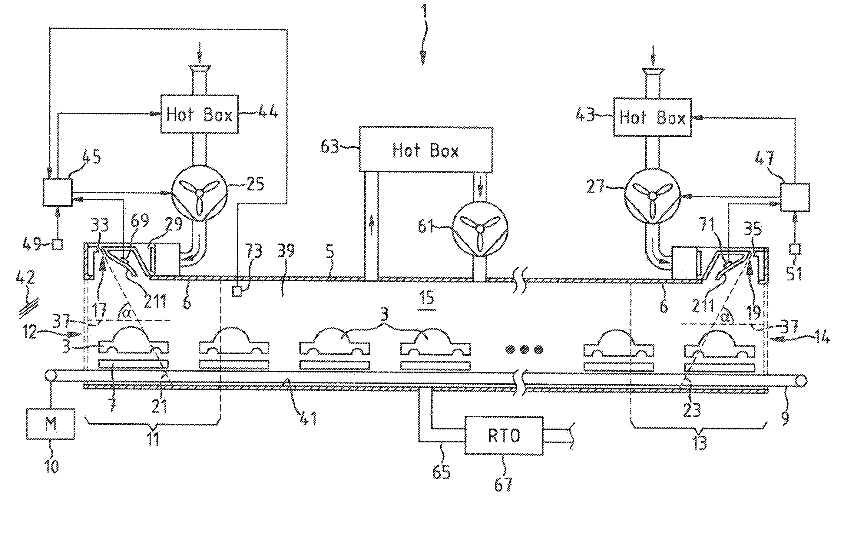
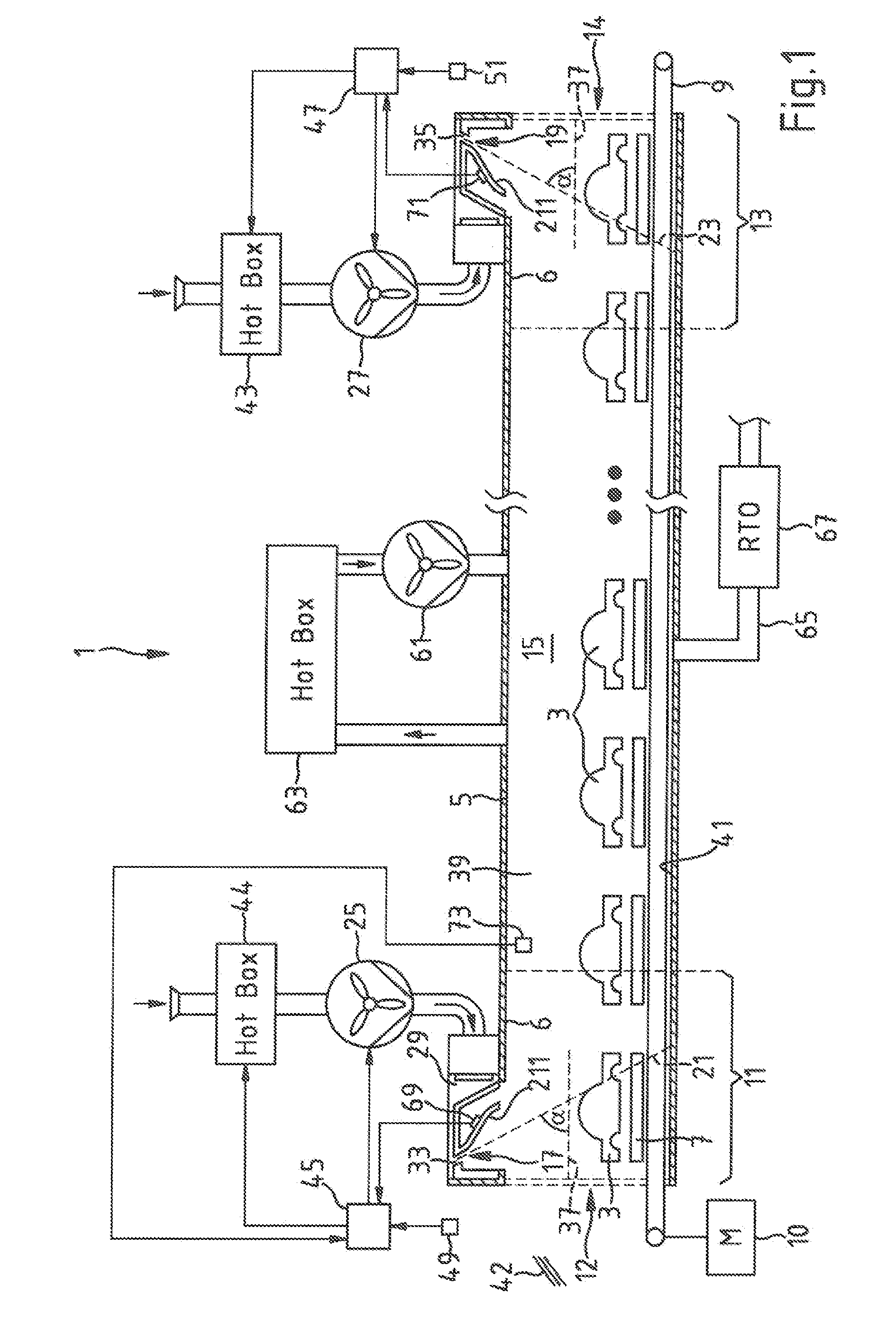
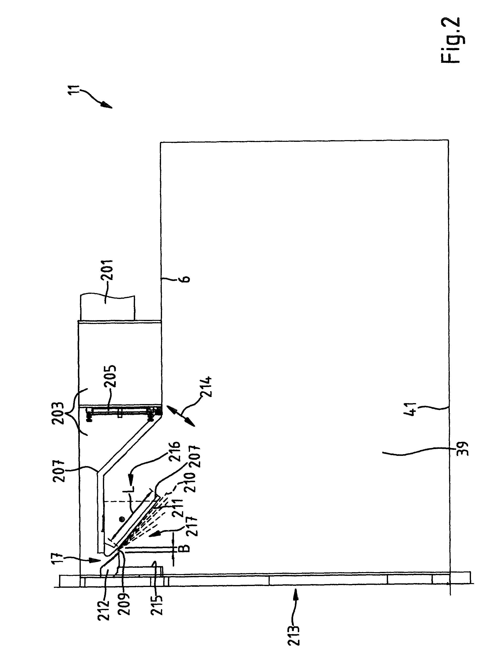
[0026]The installation 1 for drying metallic workpieces that is shown in FIG. 1 is designed in particular for vehicle bodies 3. The installation 1 comprises a process chamber formed as a drying tunnel 5. The vehicle bodies 3, which are mounted on skids 7, can foe moved through the drying tunnel 5 by a conveying device 9. The conveying device 9 has an electric drive 10. The drying tunnel 5 is lined with sheet metal.

[0027]The tunnel 5 has an intake lock 11 with an opening 12 and an exit lock. 13 with an opening 14. The drying tunnel 5 comprises a drying section 15, which lies between the intake lock 11 and the exit lock 13. The drying section 15 is a receiving region for workpieces. The drying section 15 is preferably configured such that approximately fifteen vehicle bodies 3 freshly coated with a paint and / or a solvent containing substrate can be dried therein more or less at the same time. For this purpose, the drying section 15 is designed, for example, with a length L=40 m, a cle...


PUM


Abstract

A process chamber (5) has an interior space (39). In the interior space (39), there is a receiving region (15) for workplaces (3). The process chamber (5) has an opening (12, 14) for the entry and exit of workplaces (3). The process chamber includes an arrangement (17, 19, 25, 29, 33, 37, 35) for injecting gaseous fluid into the interior space (39). The arrangement for injecting gaseous fluid has at least one nozzle (17, 19) for producing a fluid flow curtain (21, 23) between the opening (12, 14) and the receiving region (15) for workplaces (3).

Description

CROSS REFERENCE TO RELATED APPLICATIONS[0001]This application is a continuation application of international patent application PCT / EP2011 / 066154, filed Sep. 16, 2011, designating the United States and claiming priority from German application 10 2010 043 087.0, filed Oct. 28, 2010, and the entire content of both applications is incorporated herein by reference.FIELD OF THE INVENTION[0002]The invention relates to a process chamber with an interior space comprising a receiving region for workpieces, with an opening for supplying workpieces and with a device for injecting gaseous fluid into the interior space.BACKGROUND OF THE INVENTION[0003]In production works for the painting and coating of vehicle bodies, drying installations are used for the drying of vehicle bodies that have been freshly painted or coated with an anticorrosive. These drying installations have a process chamber which is formed as a drying tunnel and into which hot air is injected. In the drying tunnel there is a d...

Claims


Application Information

Patent Timeline
Patent Type & Authority Patents(United States)
IPC IPC(8): F15C1/16F26B15/14F26B19/00F26B25/00F26B25/06F24F9/00F26B25/12F26B21/02F26B21/00F26B21/04F26B15/10B60S3/00F26B21/14F26B23/02
CPCF24F9/00F26B15/10F26B15/14F26B21/004F26B21/028F26B21/04F26B25/008F26B25/12B60S3/002F26B21/14F26B23/022F26B2210/12F26B25/14
Inventor WIELAND, DIETMARIGLAUER, OLIVERKNUESEL, CHRISTOFWINKLER, MARIUS
Owner DUERR SYST AG
Why Eureka
Try Eureka