Variable output heating control system

a heating control system and variable output technology, applied in the direction of combustion control, heating types, instruments, etc., can solve the problems of large steady-state error of output temperature, difficult fine resolution control of output temperature, and temperature overshoot of on/off control system

Active Publication Date: 2016-04-19
GUM MIKE
View PDF53 Cites 6 Cited by
  • Summary
  • Abstract
  • Description
  • Claims
  • Application Information

AI Technical Summary

Problems solved by technology

This type of on / off control system often incurs temperature overshoot, wherein the output temperature (or the ambient temperature of the house or building) rises above the temperature setting as a result of all burners turning on at maximum capacity in an attempt to raise the temperature by a small amount.
Thus, fine resolution control of the output temperature is difficult.
Alternatively, if the control system is adjusted to reduce temperature overshoot, then there is often a large steady-state error of the output temperature as compared with the set temperature, typically on the cold side, as the control system waits until the output temperature drops low enough below the set temperature to turn on all the burners at maximum capacity.
Therefore, the on / off heating control system is inefficient by using excessive energy to maintain the set temperature or is ineffective by leaving the burners off for too long resulting in a cold and uncomfortable environment.

Method used


Image

  • Variable output heating control system
  • Variable output heating control system
  • Variable output heating control system

Examples


first embodiment

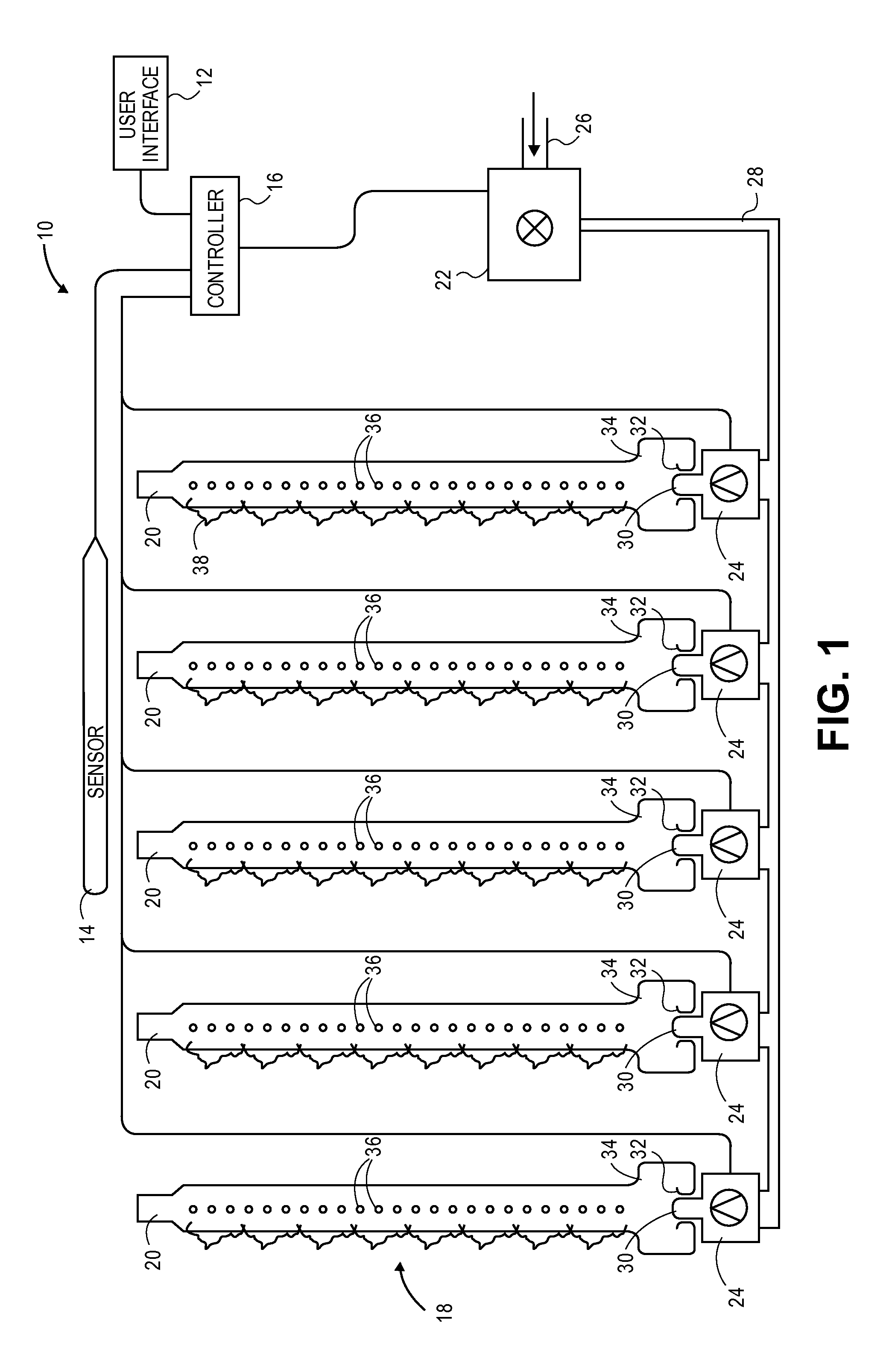
[0051]Alternatively, the controller 16 may send a signal to one or more of the shutoff valves 42 to close, without reducing the flow of gas from the modulating combination control valve 40. For example, the controller 16 may close two of the five shutoff valves 42, thereby decreasing heat output to approximately 60% of full capacity. Furthermore, the controller 16 may send a signal to one or more of the shutoff valves 42 to close, in addition to sending a signal to the modulating combination control valve 40 to reduce the flow of gas. For example, the controller 16 may close two of the five shutoff valves 42 and reduce the gas flow rate to 50%, thus leaving three burners 20 on, each receiving 50% gas flow rate, thereby reducing heat output to approximately 30% of full value. As with the first embodiment discussed above, how many shutoff valves 42 are closed and how the flow rate is reduced may depend on a plurality of factors such as the rate at which the measured temperature is app...

fifth embodiment

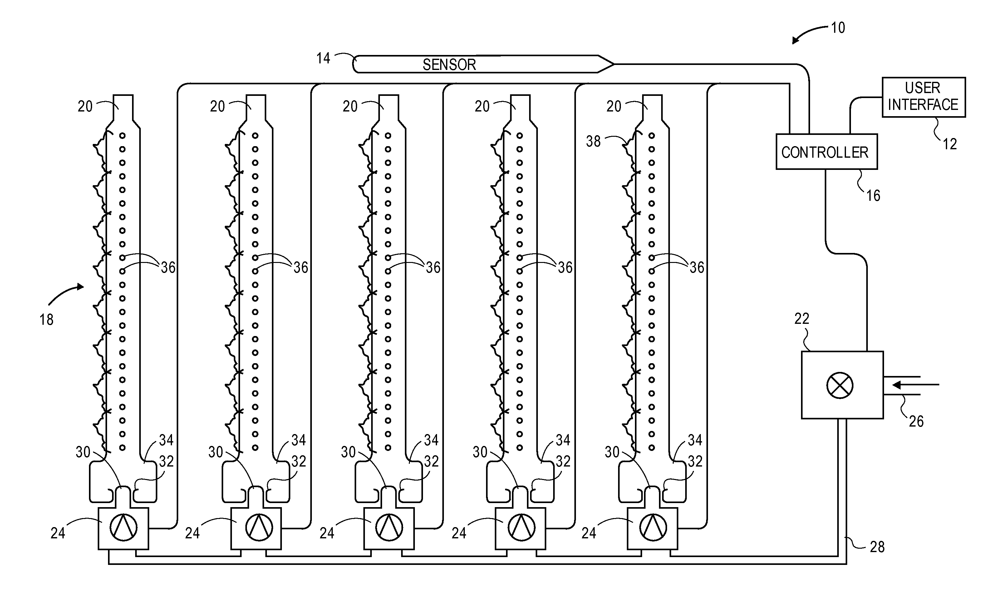
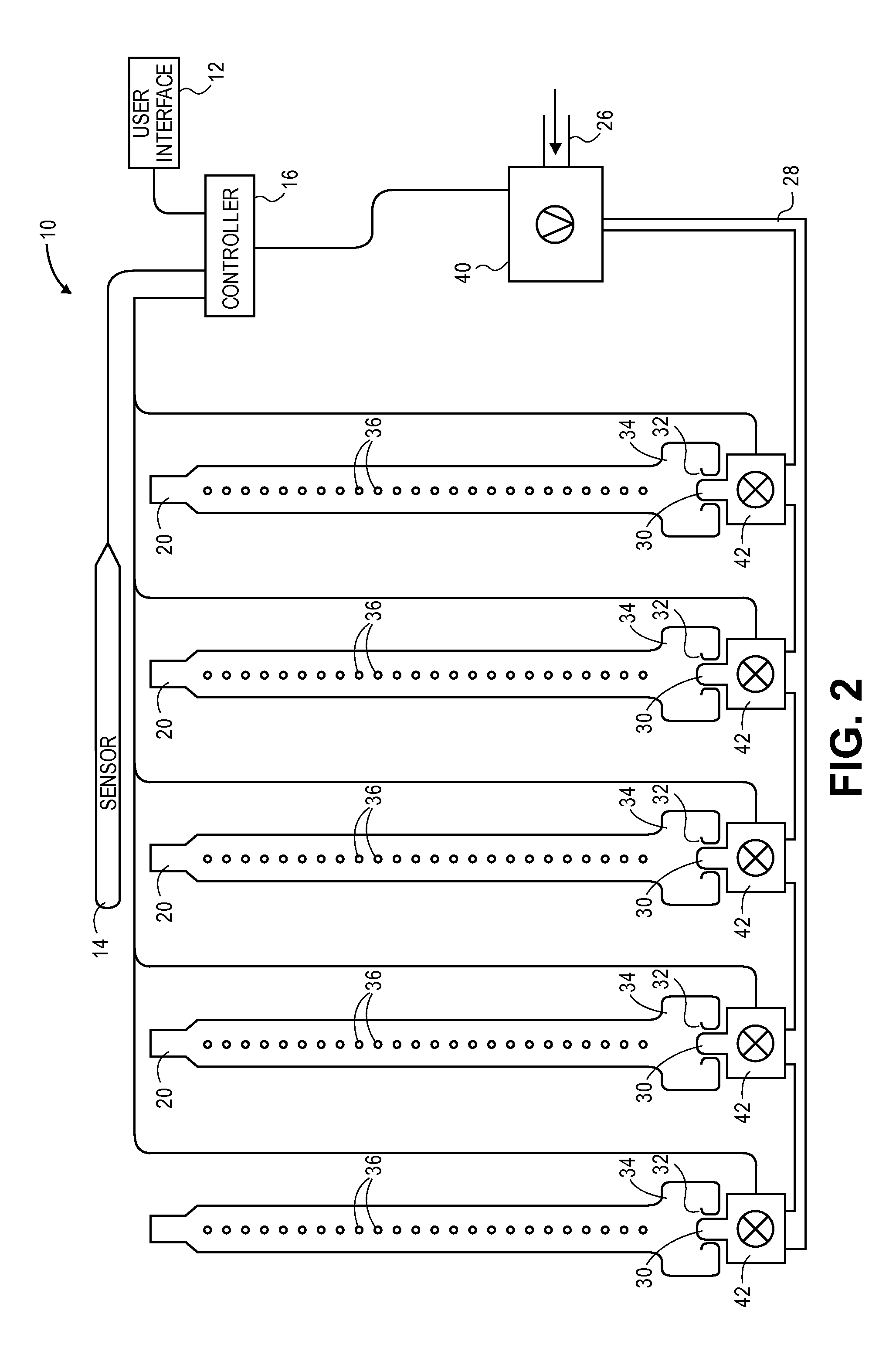
[0055]Another exemplary embodiment of the variable output heating control system 10 is shown in FIG. 5. The system 10 of the fifth embodiment may comprise a user interface 12, an operating parameter sensor 14, a controller 16, a plurality of burners 20, a combination control valve 22, and a shutoff valve 42. These components operate in a substantially similar fashion as described above. The combination control valve 22 controls the flow of gas to a plurality of burners 20 through a standard orifice 44. Thus, the combination control valve 22 may shut off the flow of gas to the burners 20. The shutoff valve 42 may be coupled to at least one of the burners 20, as depicted in FIG. 5, allowing the ability to shut off the flow of gas to only those burners 20 coupled to a shutoff valve 42. This embodiment of the system 10 can provide temperature control by shutting off one or more selected burners without adding modulation controls, which may be more expensive.

[0056]The variable output hea...


PUM


Abstract

A variable output heating control system includes a user interface, an operating parameter sensor, a controller, a combination control valve, a plurality of variable flow valves, and a plurality of burners. The user interface allows a user to enter operating parameters, such as a set temperature. The operating parameters sensor provides measured parameters, such as a measured temperature. The controller receives the set temperature and the measured temperature and generates commands to control the flow of gas, based on the set temperature and the measured temperature. The combination control valve shuts off the flow of gas from an external gas source based on a command from the controller. The plurality of variable flow valves vary the flow of gas that is received from the combination control valve and supplied to the burners. The plurality of burners provide heat based on the combustion of gas that is received from the plurality of variable flow valves.

Description

BACKGROUND OF THE INVENTION[0001]1. Field of the Invention[0002]Embodiments of the present invention relate to systems and methods for controlling combustible fuel heating systems. More particularly, embodiments of the present invention relate to systems and methods for controlling gas flow to individual or multiple burners in a combustible fuel heating system.[0003]2. Description of the Related Art[0004]Residential and commercial gas furnace systems typically employ multiple burners to provide sufficient heating capacity. Generally, a combination control valve controls the supply of fuel from a fuel source to the burners in an on / off fashion, such that all the burners are either fully on or fully off. The furnace cannot turn on individual burners nor can it vary the flow of gas to the burners. This type of on / off control system often incurs temperature overshoot, wherein the output temperature (or the ambient temperature of the house or building) rises above the temperature setting...

Claims


Application Information

Patent Timeline
Patent Type & Authority Patents(United States)
IPC IPC(8): F24D10/00G05D7/00F24H9/20F23N1/00F23N5/02F24H1/46F24D19/10F24D12/02G05D23/00F24D19/00G05D23/19
CPCF23N1/005F23N5/025F24D12/02F24D19/1006F24H1/46G05D23/19F24H9/2035Y02B30/14F23N2025/08F23N2037/02F24D2200/043F24D19/1084F23N2225/08F23N2237/02Y02B30/00F24H15/242F24H15/414F24H15/281F24H15/238F24H15/31F24H15/45F24H15/254F24H15/172
Inventor GUM, MIKE
Owner GUM MIKE
Why Eureka
Try Eureka