
Apparatus and method to inspect, modify, or repair nuclear reactor core shrouds

a technology for nuclear reactors and shrouds, applied in nuclear engineering, nuclear elements, greenhouse gas reduction, etc., can solve the problems of shrinking the shroud, increasing the risk of loss-of-coolant accidents, and reducing the structural integrity of the shroud

Active Publication Date: 2016-04-19
WESTINGHOUSE ELECTRIC CORP
View PDF12 Cites 0 Cited by
  • Summary
  • Abstract
  • Description
  • Claims
  • Application Information

AI Technical Summary

Problems solved by technology

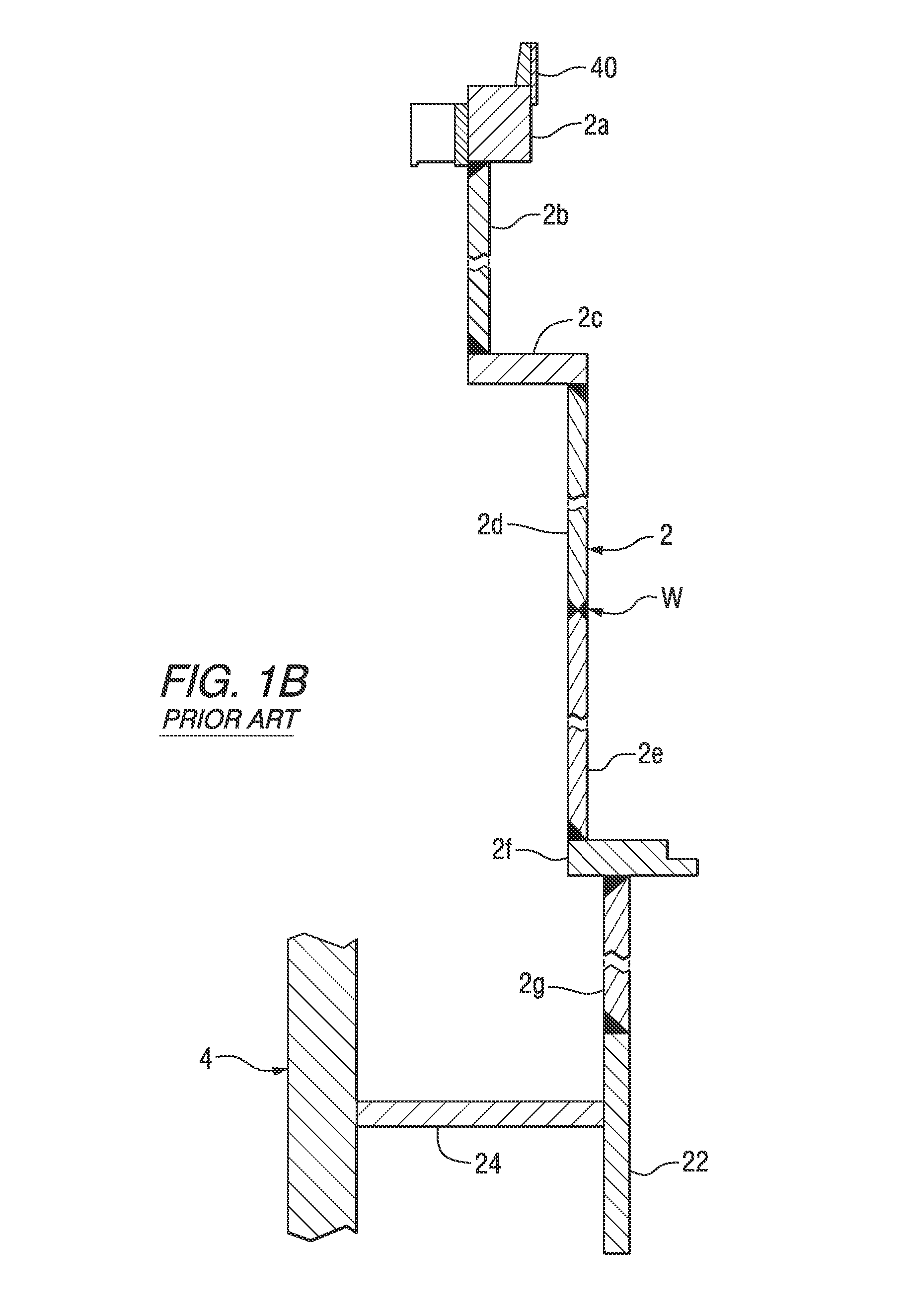
Therefore, the mechanisms are present for the shroud welds to be susceptible to stress corrosion cracking.
Stress corrosion cracking in the heat affected zone of any shroud weld diminishes the structural integrity of the shroud.
In particular, a cracked shroud increases the risks posed by a Loss-of-Coolant Accident (LOCA) or seismic loads.
If the core shroud has fully cracked girth welds, the lifting forces produced during a LOCA could cause the shroud to separate along the areas of cracking, producing undesirable leaking of reactor coolant.
Also, if the shroud weld zones fail due to stress corrosion cracking, there is a risk of misalignment from seismic loads and damage to the core and the control rod components, which would adversely affect control rod insertion and safe shutdown.
However, the core shroud is difficult to access.
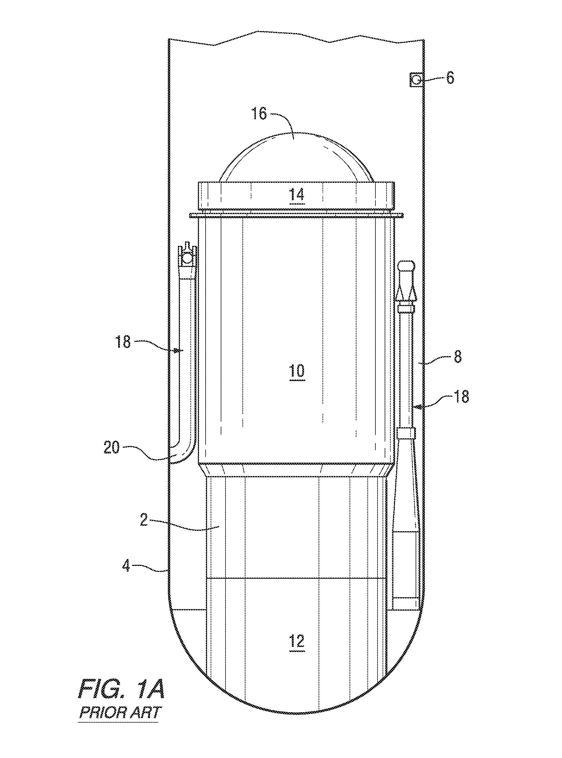
Installation access is limited to the annular space between the outside of the shroud and the inside of the reactor pressure vessel, between adjacent jet pumps.
Scanning operation access is additionally restricted within the narrow space between the shroud and jet pumps.
Remote operation is mandatory due to safety risks associated with radiation in the reactor.
Relatively long durations are required to install or remove manipulators and can impact the plant shutdown duration.
The long durations cannot only impact plant shutdown durations, but also increase personnel radiation and contamination exposure.
Therefore, the size of the manipulators can impact other activities during plant shutdown.

Method used


Image

  • Apparatus and method to inspect, modify, or repair nuclear reactor core shrouds
  • Apparatus and method to inspect, modify, or repair nuclear reactor core shrouds
  • Apparatus and method to inspect, modify, or repair nuclear reactor core shrouds

Examples


Embodiment Construction

[0024]It will be understood that, although the terms first, second, etc. may be used herein to describe various elements, these elements should not be limited by these terms. There terms are only used to distinguish one element from another. For example, a first element could be termed a second element, and similarly, a second element could be termed a first element, without departing from the scope of the embodiments. As used herein, the term “and / or” includes any and all combinations of one or more of the associated listed items.

[0025]It should be understood that when an element of component is referred to as being “on”, “connected to,”“coupled to,” or “covering” another element or layer, it may be directly on, connected to, coupled to, or covering the other element or layer or intervening elements or components may be present.

[0026]Spatially relative terms (e.g., “beneath,”“below,”“lower,”“above,”“upper,” and the like) may be used herein for ease of description to describe one el...


PUM


Abstract

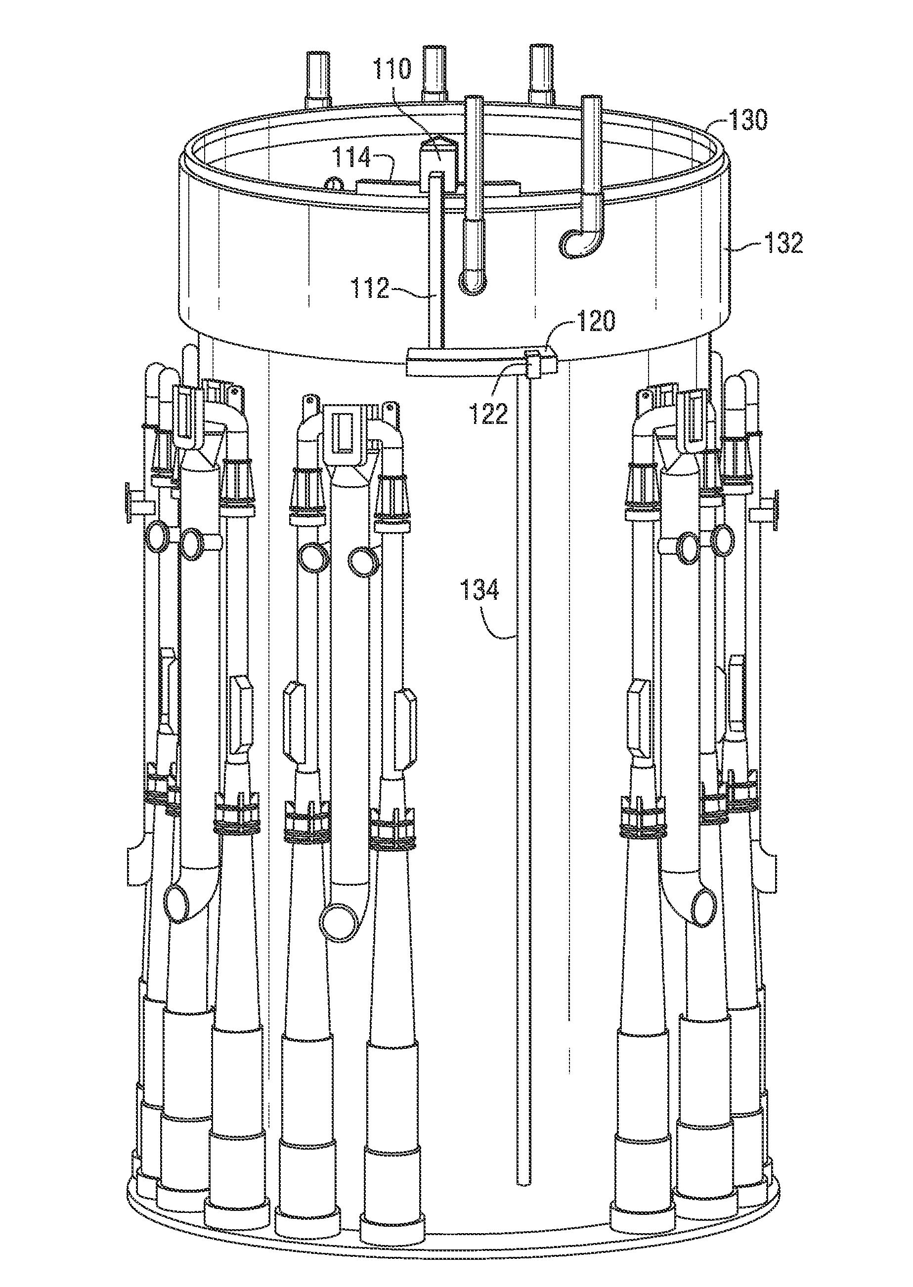
This invention generally concerns robotic systems and is particularly concerned with improved apparatus and methods for remotely inspecting, modifying or repairing a core shroud in a nuclear reactor. The apparatus of the invention includes a partial upper track which horizontally movable along the core shroud, a head and frame assembly which is horizontally movable along the partial upper track, a lower track which is connected to the head and frame assembly and is horizontally movable along the core shroud, and a carriage and arm assembly which extends downward into an annulus formed by the reactor pressure vessel and the core shroud, wherein the arm includes at least one sensor for inspecting the core shroud.

Description

CROSS-REFERENCE TO RELATED APPLICATIONS[0001]This application claims priority under 35 U.S.C. Section 119(e) from Provisional Application 61 / 711,240, entitled “Apparatus and Method to Inspect, Modify, or Repair Nuclear Reactor Core Shrouds” filed on Oct. 9, 2012.FIELD OF THE INVENTION[0002]This invention generally concerns robotic systems and is specifically concerned with an improved apparatus and method for remotely inspecting, modifying or repairing a core shroud in a nuclear reactor.BACKGROUND OF THE INVENTION[0003]A nuclear reactor produces electrical power by heating water in a reactor pressure vessel that contains a nuclear fuel core in order to generate steam which is used in turn to drive a steam turbine. The reactor pressure vessel includes a cylinder surrounding the nuclear fuel core. This cylinder is the core shroud. Feed water is admitted into the reactor pressure vessel and flows through an annular region which is formed between the reactor pressure vessel and the core...

Claims


Application Information

Patent Timeline
Patent Type & Authority Patents(United States)
IPC IPC(8): G21C17/013G21C17/003G21C17/007
CPCG21C17/013G21C17/003G21C17/007G21F3/00Y02E30/30
Inventor FOLEY, KEVIN J.EVERETT, MARK STEVEBARRETT, CHARLES R.
Owner WESTINGHOUSE ELECTRIC CORP
Learn More