Electromagnetic actuating device

a technology of actuating device and actuating device, which is applied in the direction of electromagnets, electrical apparatus, basic electric elements, etc., can solve the problems of sensor unit b>22/b> not being able to reliably acquire the end position of the plunger, complex downstream evaluation electronics, and being prone to failure. , to achieve the effect of simple and effectiv

Active Publication Date: 2016-04-19
ETO MAGNETIC GMBH
View PDF24 Cites 7 Cited by
  • Summary
  • Abstract
  • Description
  • Claims
  • Application Information

AI Technical Summary

Benefits of technology

[0014]In a manner advantageous according to the invention, the described device, more precisely the coil unit, additionally has allocated to it flux-directing means, which are designed in such a way as to suitably dissipate or shield a magnetic coil field generated by the coil unit in an energized state away from the magnetic field detecting means, and / or weaken it relative to the magnetic field detecting means. Therefore, the object of the present invention is to improve the detection characteristics of a generic device that additionally exhibits stationary magnetic field detecting means for interaction with permanent magnet means moved by armature motion so as to detect position and movement, in particular to overcome any damaging influence by a magnetic coil field.
[0019]Within the framework of preferred forms of realization for the invention, the slide or plunger unit is here detachably joined with the armature unit, and specifically in such a way that the permanent magnetic force exerted by the permanent magnet means holds the plunger unit (detachably) to the armature unit. As a result, the permanent magnet unit is exposed to a multiple synergistic effect: on the one hand, its repelling force when the coil is energized ensures that the armature moves within the framework of the electromagnetic actuating function of the actuating device. On the other hand, as discussed, it provides the opportunity to use the stationary magnetic field detecting means (for example, realized as a stationary sensor unit) to reliably detect an armature motion and position at any time, while the permanent magnet unit additionally and advantageously establishes the reliable and at once detachable connection between the slide or plunger unit and armature unit (for example, in a preferred case by virtue of the fact that the armature unit itself exhibits suitable permanent magnet means, e.g., a correspondingly magnetized disk, and the plunger unit then consists of magnetically conductive material, e.g., soft iron).
[0023]As a result, the present invention makes it possible to improve the technology already known from internal prior art in terms of its detection characteristics, in particular its insensitivity to any magnetic field influences of the energized coil, in a surprisingly simple and effective way, and thereby to also make the present invention accessible in demanding or problematic conditions of use in terms of magnetic flux.

Problems solved by technology

It is precisely within the context of an internal combustion engine or similar field of application that reliable operation becomes especially critical, wherein the special environmental conditions (high temperature, vibration, potentially frosty engine) can lead to occasional malfunctions, which have to be reliably detected.
However, the disadvantage to this technology in conjunction with other similar approaches from prior art not delved into in any greater detail here is that a malfunction can only be ascertained from a respective terminal signal with difficulty, which accordingly makes downstream evaluation electronics complicated and itself prone to failure in turn.
Add to the above the disadvantage that this known induction technology can by principle only detect a movement by the plunger or armature unit, but not a respective plunger position; in particular, means for evaluating an induction coil voltage do not make it possible to reliably acquire a (standing) end position of the plunger, for example as it engages into the camshaft.
However, taking into account a coil field always present when the coil unit 10 is being energized (see field lines 11 in this regard), it turns out that the latter can cause the sensor unit 22 to malfunction when overlapped.

Method used


Image

  • Electromagnetic actuating device
  • Electromagnetic actuating device
  • Electromagnetic actuating device

Examples


Embodiment Construction

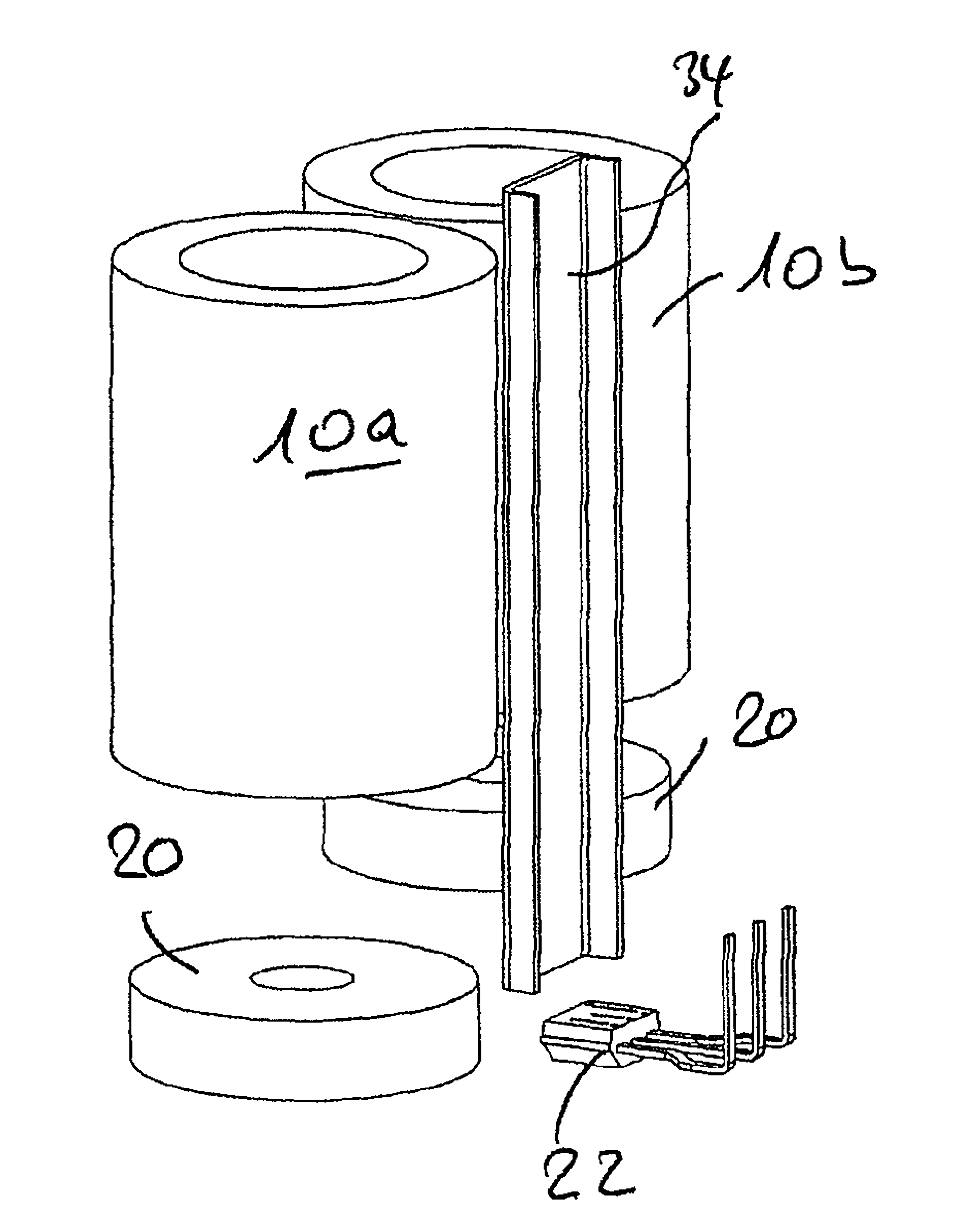
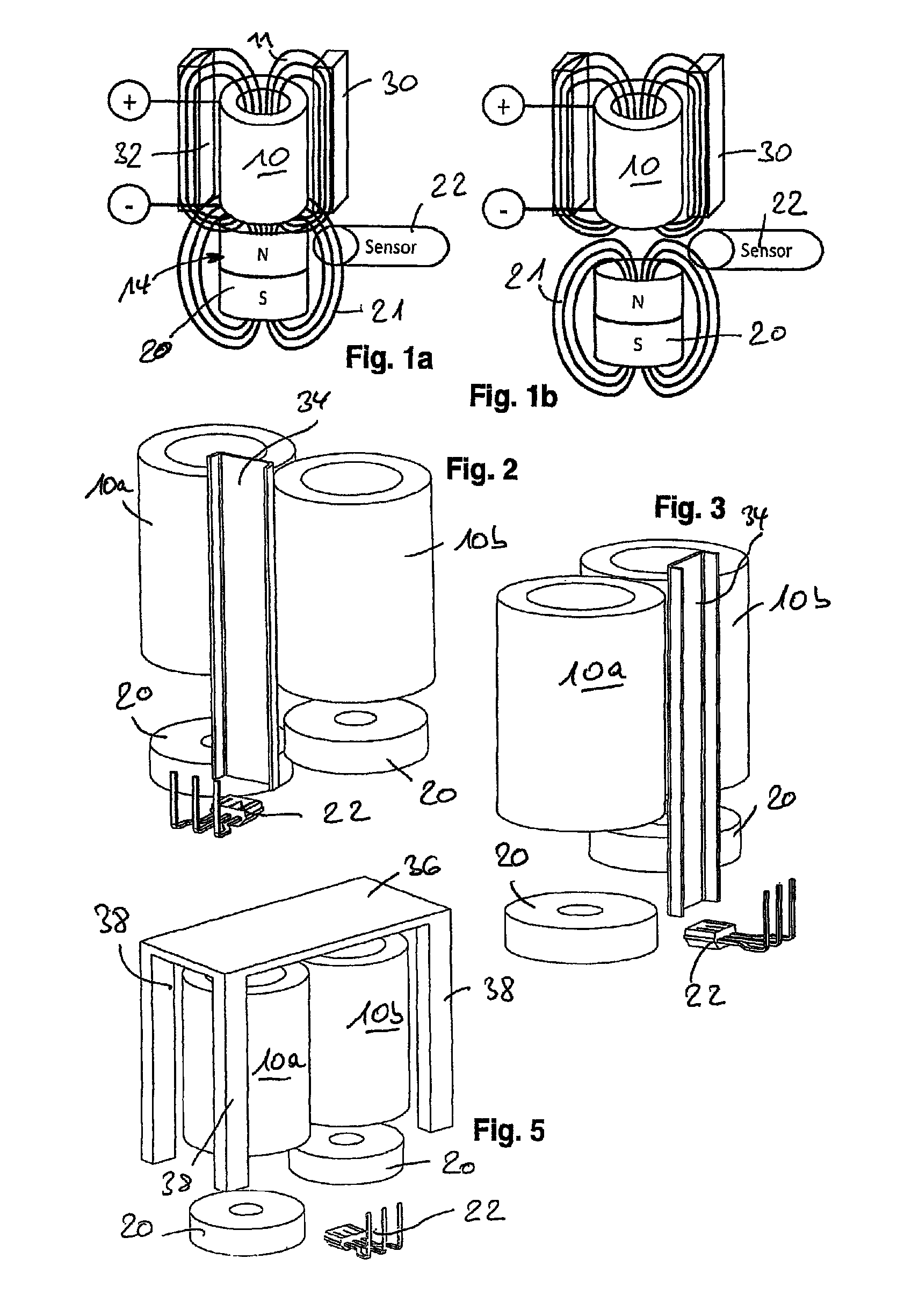
[0035]Similarly to the view on FIG. 11a, 11b regarding internal prior art, the comparison on FIG. 1a, 1b (once more for the energized state of the armature unit (FIG. 1a), with armature unit 14 as the permanent magnetic unit 20 at the top of the image on the coil 11, and in the deenergized state on FIG. 1b, with the armature unit (again with only the permanent magnetic unit 20 shown) at the bottom of the figure plane) illustrates that elongated flux-directing elements 30, 32 provided additionally and adjacent to the coil unit 10, which extend axially parallel to the longitudinal axis through the coil unit 10 (which to this extent also describes the axis of motion for the armature), bundle the coil magnetic field 11 generated by energizing the coil in its flux-directing elements. In the practical geometric realization on FIG. 1a, 1b, the effect of this is that the coil magnetic field does not extend as far in an axial direction, and thus no longer reaches the sensor 22 (or its sensit...


PUM

PropertyMeasurementUnit
magnetic fieldaaaaaaaaaa
magnetic fluxaaaaaaaaaa
magnetically conductiveaaaaaaaaaa

Abstract

An electromagnetic actuating device, in particular camshaft adjustment device, having an armature unit (14) which can be driven in the axial direction or parallel thereto in reaction to energization of a stationary, axially oriented coil unit (10) and is designed to interact with a slide and / or plunger unit (16) which extends in the axial direction, in particular a plunger unit which brings about camshaft adjustment of an internal combustion engine, wherein permanent magnet means are provided on and / or in the armature unit and / or the slide or plunger unit, and the coil unit and armature unit are accommodated at least partially in a housing unit or carrier unit.

Description

BACKGROUND OF THE INVENTION[0001]The present invention relates to an electromagnetic actuating device. For example, such devices are known from German Utility Model 201 14 466, and are suitable for numerous actuating devices. A known application for such a device involves camshaft adjustment; the slide or plunger unit connected with the movable armature unit here acts on a camshaft of an internal combustion engine, thereby creating a desired adjustment functionality.[0002]It is precisely within the context of an internal combustion engine or similar field of application that reliable operation becomes especially critical, wherein the special environmental conditions (high temperature, vibration, potentially frosty engine) can lead to occasional malfunctions, which have to be reliably detected. Correspondingly, so-called reset acquisition technologies are known from prior art for electromagnetic actuating device, wherein an induction signal of the armature unit moving in accordance w...

Claims


Application Information

Patent Timeline
Patent Type & Authority Patents(United States)
IPC IPC(8): H01F7/08H01F7/16F01L13/00F01L1/047H01F7/121H01F7/18
CPCH01F7/121F01L1/047F01L13/0036H01F7/1646H01F7/1844F01L2013/0052F01L2820/031
Inventor SCHIEPP, THOMASSCHOELLER, STEFANBUERSSNER, JOERGVINCON, PETER
Owner ETO MAGNETIC GMBH
Why Eureka
Try Eureka