Fiber optic connector

a fiber optic connector and fiber optic technology, applied in the field of fiber optic connectors, can solve the problems of difficult laser processing of short glass fiber protruding, zirconia may not survive direct contact with high laser power, and the overall appearance of a conventional ferrule is maintained. , to achieve the effect of facilitating laser-forming and processing of optical fibers, providing strength and durability for ferrules, and maintaining the overall appearance of conventional ferrules

Active Publication Date: 2016-04-26
CORNING OPTICAL COMM LLC
View PDF35 Cites 28 Cited by
  • Summary
  • Abstract
  • Description
  • Claims
  • Application Information

AI Technical Summary

Benefits of technology

[0008]In some embodiments, an outer piece of the ferrule includes zirconia to provide strength and durability for the ferrule, while maintaining the overall appearance of a conventional ferrule. An inner piece of the ferrule includes a material, such as fused silica, that melts and / or ablates in a manner similar to silica-based optical fibers. The ferrule facilitates laser-forming and processing of the optical fiber in one process step, and the inner piece may subsequently be inserted into and secured within the outer piece of the ferrule.

Problems solved by technology

One problem with zirconia ferrules is that the zirconia may not survive direct contact with high quantities of laser power.
Contact with the laser beam may cause micro-cracking of the zirconia.
Therefore it is generally difficult to laser process a short glass fiber protruding from the zirconia ferrule.

Method used


Image

  • Fiber optic connector
  • Fiber optic connector
  • Fiber optic connector

Examples


Embodiment Construction

[0025]Before turning to the Figures, which illustrate exemplary embodiments now described in detail, it should be understood that the present inventive and innovative technology is not limited to the details or methodology set forth in the Detailed Description or illustrated in the Figures. For example, as will be understood by those of ordinary skill in the art, features and attributes associated with embodiments shown in one of the Figures may be applied to embodiments shown in others of the Figures.

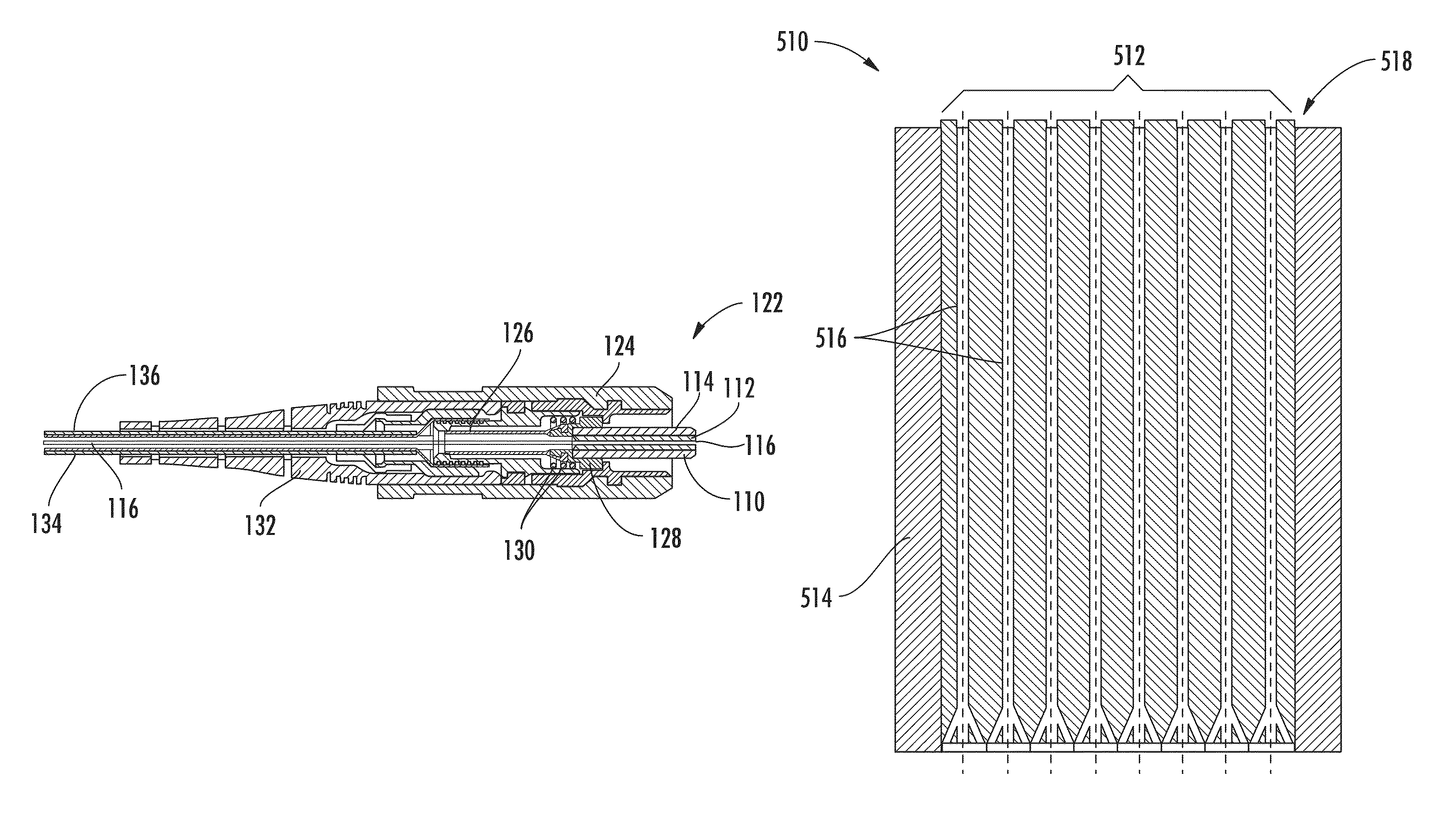
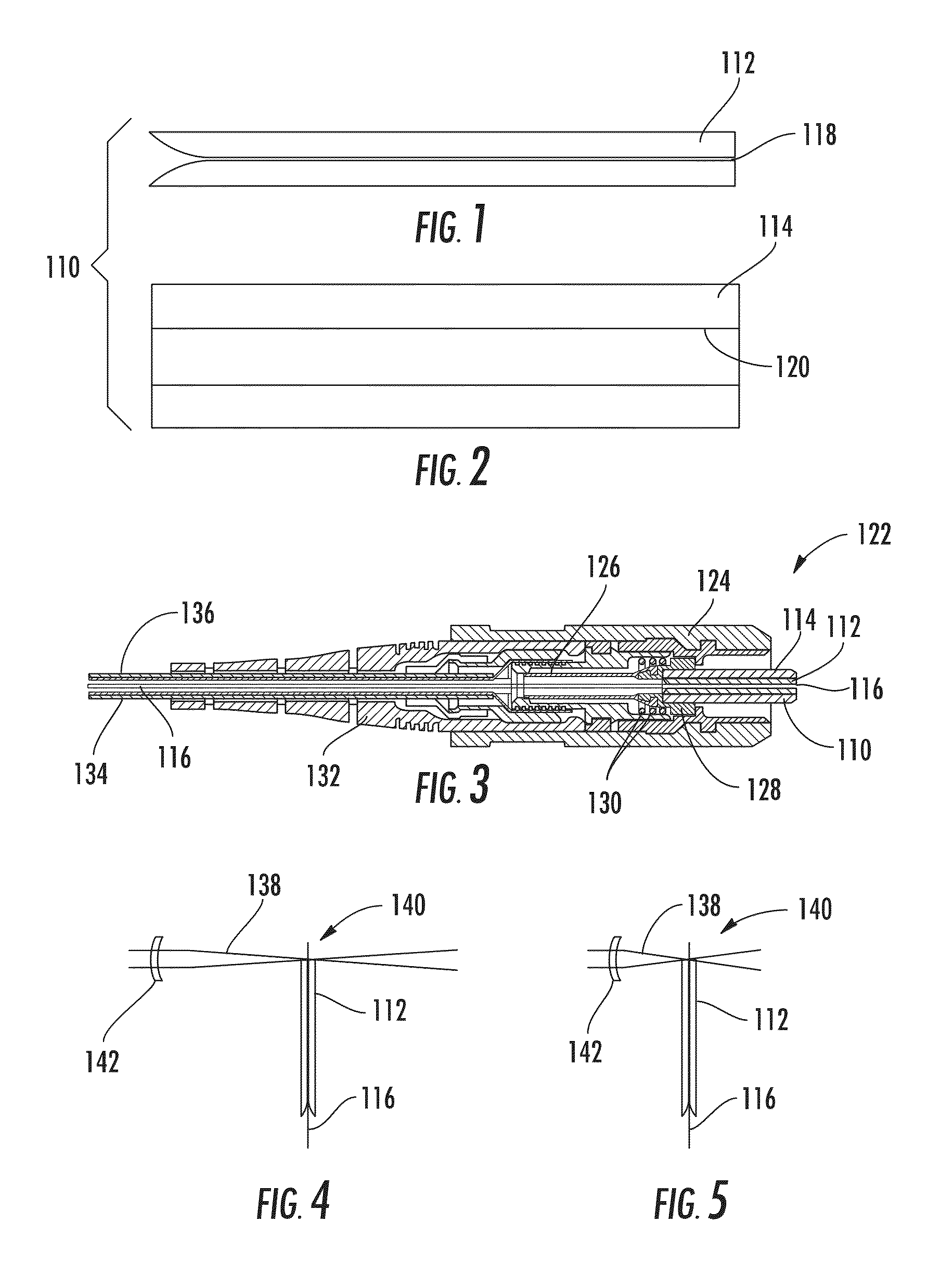
[0026]Referring to FIGS. 1-2, a ferrule 110 (e.g., composite ferrule, two-piece ferrule) includes an inner piece 112 (e.g., inner ferrule, insert, first structure; see FIG. 1) and an outer piece 114 (e.g., exterior ferrule, shell, second structure; see FIG. 2). The inner piece 112 includes a bore 118 for an optical fiber 116 (FIG. 3) and the inner piece 112 is sized and configured to fit into an interior passage 120 (e.g., bore) defined by the outer piece 114. In some embodiments, the ...


PUM

PropertyMeasurementUnit
heightaaaaaaaaaa
heightaaaaaaaaaa
lengthaaaaaaaaaa

Abstract

A fiber optic connector includes a ferrule. The ferrule includes an inner piece including silica and an outer piece including ceramic. The outer piece surrounds the inner piece and the inner piece extends beyond an end of the outer piece by a distance of at least 10 micrometers.

Description

RELATED CASES[0001]This application claims the benefit of priority under 35 U.S.C. §119 of U.S. Provisional Application Ser. No. 61 / 752,697 filed on Jan. 15, 2013 the content of which is relied upon and incorporated herein by reference in its entirety.BACKGROUND[0002]Aspects of the present disclosure relate generally to fiber optic connectors, ferrules that may be used with fiber optic connectors, and methods of manufacturing ferrules and connectors.[0003]Ferrules in use today are often made of zirconia because zirconia ferrules tend to be particularly durable and the manufacturers can produce zirconia ferrules with high-precision dimensional tolerances at very low cost. The color of zirconia ferrules is generally a distinct glossy white and their overall appearance is generally the same, regardless of the manufacturer.[0004]Mechanical polishing is typically used when manufacturing fiber optic connectors with ferrules and associated optical fibers because mechanical polishing is an ...

Claims


Application Information

Patent Timeline
Patent Type & Authority Patents(United States)
IPC IPC(8): G02B6/25G02B6/245G02B6/38
CPCG02B6/25G02B6/3854G02B6/3863B23K26/082G02B6/3846G02B6/3885
Inventor MILLER, DARRIN MAX
Owner CORNING OPTICAL COMM LLC
Why Eureka
Try Eureka