
Multi-layered foil body

a technology of multi-layered foil and foil body, which is applied in the direction of printing, printing process, instruments, etc., can solve the problems of difficult to see the variations of optical appearance produced by such a security element in unfavorable light conditions, and the level of protection against forgery that can be achieved therewith is thus relatively limited, so as to improve the appearance of the optical

Active Publication Date: 2016-04-26
LEONHARD KURZ STIFTUNG & CO KG +1
View PDF17 Cites 1 Cited by
  • Summary
  • Abstract
  • Description
  • Claims
  • Application Information

AI Technical Summary

Benefits of technology

The invention aims to enhance the appearance of an optically variable security feature.

Problems solved by technology

The variations in optical appearance that can be produced by such a security element are often difficult to see under unfavorable light conditions and not conspicuous enough for the “man on the street”.
The level of protection against forgery that can be achieved therewith is thus relatively limited.

Method used


Image

  • Multi-layered foil body
  • Multi-layered foil body
  • Multi-layered foil body

Examples


Embodiment Construction

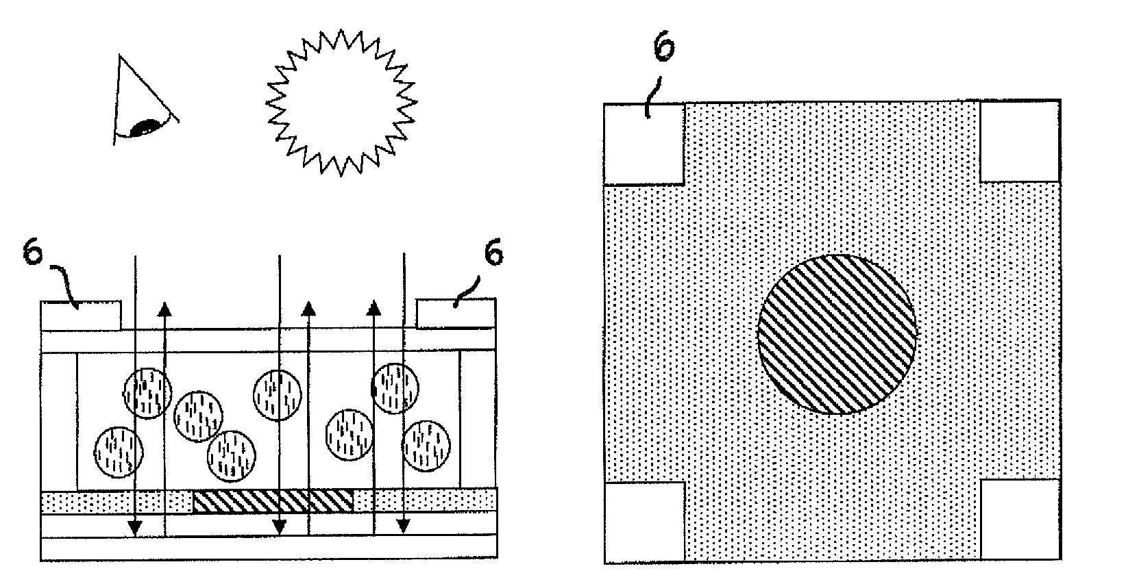
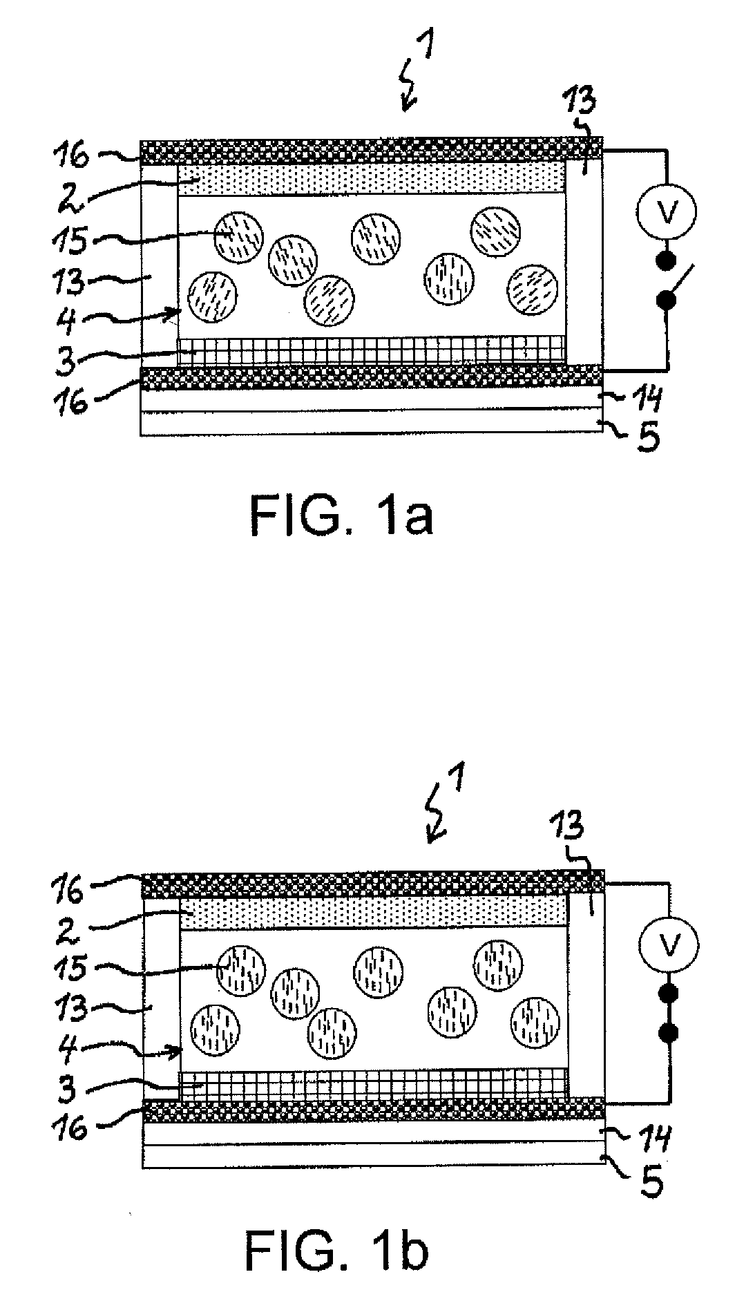
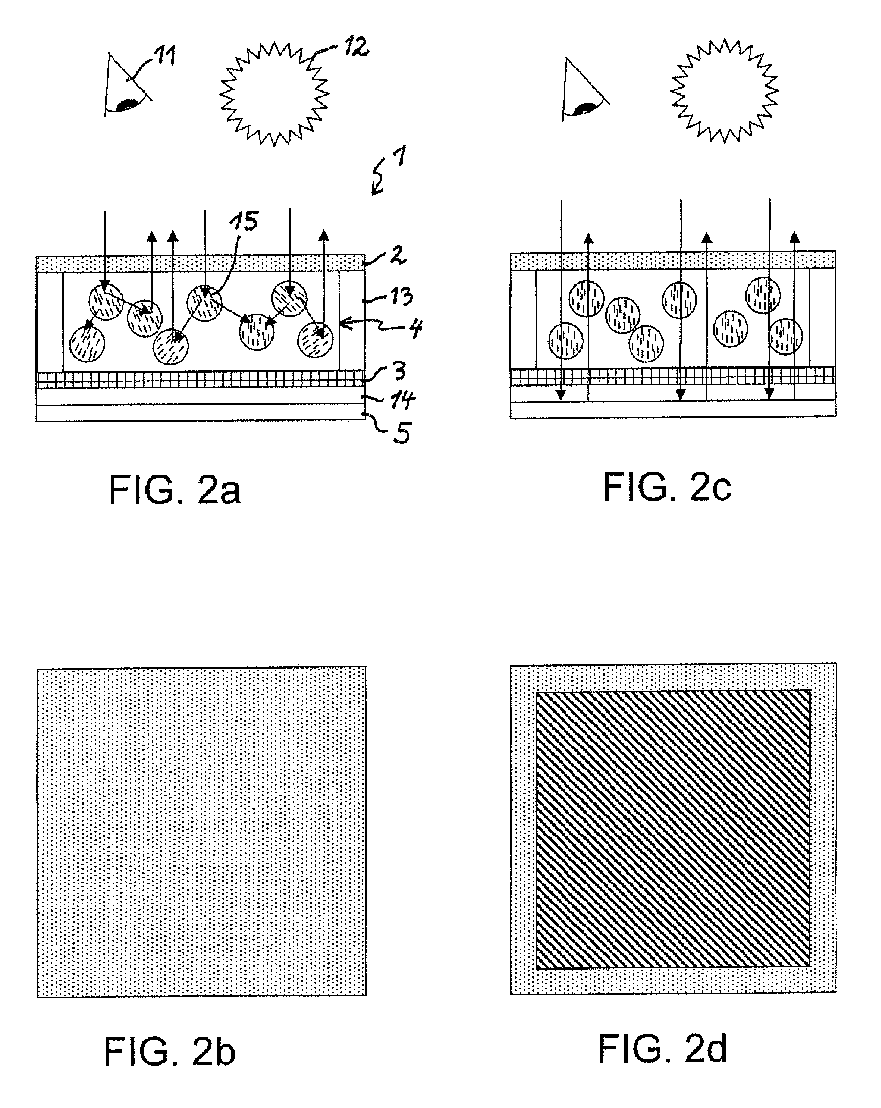
[0063]FIG. 1 shows a multi-layered foil body 1 with a first color filter layer 2, a change layer 4 in the form of a PDLC layer, a second color filter layer 3, an auxiliary layer 14 and a reflective layer 5. The foil body 1 can be attached to a substrate e.g. by means of an adhesive layer, wherein the adhesive layer is arranged between the reflective layer 5 and the substrate. Both sides of the PDLC layer 4 are at least partially covered by electrodes 16, i.e. a first and a second electrode layer 16, to which a voltage V can be applied to generate an electric field between the electrodes 16. The upper electrode 16 is preferably transparent, translucent or semi-transparent, e.g. consisting of ITO or of metal areas with small layer thickness, in particular in grid or grating form. The lower and / or upper electrode 16 can have a diffractive surface relief, wherein an electrically conductive metallic or HRI electrode layer acts as optical reflective layer for this.

[0064]If the change laye...


PUM

PropertyMeasurementUnit
thicknessaaaaaaaaaa
thicknessaaaaaaaaaa
thicknessaaaaaaaaaa

Abstract

The invention relates to a multi-layered foil body (1) for marking a security document, in particular a banknote. The foil body (1) has at least one color filter layer (2) and at least one change layer (4) with an electrically controllable transmittance and / or an electrically controllable color.

Description

[0001]This application claims priority based on an International Application filed under the Patent Cooperation Treaty, PCT / EP2012 / 062298, filed on Jun. 26, 2012, and German Application No. DE 102011107421.3, filed on Jul. 7, 2011.BACKGROUND OF THE INVENTION[0002]The invention relates to a multi-layered foil body, a security element with at least one foil body, a security document with at least one foil body, a transfer foil with at least one foil body as well as a method for producing a multi-layered foil body.[0003]WO 2009 / 043482 A1 describes a security element for the identification of a security document such as a banknote. The security element has a multi-layered foil body with a PDLC layer which reversibly changes from a scattering state into a transparent state when an electric field is applied (PDLC=Polymer Dispersed Liquid Crystal). This change in transmission is controlled by a piezoelectric energy source of the security element: when a piezoelectric material of the energy...

Claims


Application Information

Patent Timeline
Patent Type & Authority Patents(United States)
IPC IPC(8): G02F1/1335B42D25/29B42D25/00G02F1/01G02B26/02B42D25/328G02F1/1334B41M3/14
CPCG02F1/133514B42D25/00B42D25/29G02B26/02G02F1/0102G02F1/133516B41M3/14B42D25/328G02F1/1334B42D25/351B42D25/355B42D25/36B42D25/364B42D25/45G03H1/0011
Inventor STAHL, RAINERTOMPKIN, WAYNE ROBERTWALTER, HARALD
Owner LEONHARD KURZ STIFTUNG & CO KG
Learn More