
Propulsion system for use by a swimmer

a technology for propulsion systems and swimmers, applied in swimming frameworks, underwater equipment, swimming, etc., can solve problems such as limiting the degree of control of the system, increasing the chance of snagging, and affecting the speed of the system

Active Publication Date: 2016-05-03
PROPULSE LLC
View PDF7 Cites 9 Cited by
  • Summary
  • Abstract
  • Description
  • Claims
  • Application Information

AI Technical Summary

Benefits of technology

[0012]It is an object of the invention to provide a diver with a personally powered propulsion system which enables a user to have a high degree of maneuverability upon and under the water.
[0013]It is another object to provide an efficient and effective personal power propulsion system for swimmers and divers which enables the user to have enhanced maneuverability in and under the water and which, during use, can leave the user's hands free for the performance of desired tasks or actions.
[0015]It is a yet further object to provide a completely hand and wrist-operated under or in-water propulsion system attachable to the forearm of the swimmer in which speed and directionality can be fully controlled by the hand and wrist of the swimmer.

Problems solved by technology

However, in that each unit is fixed and parallel with the forearm, it offers no degree of movement other than that which is physiologically possible by the forearm of the swimmer.
Such cables and harness inherently encumber the swimmer or diver who must at all times be aware of the harness on the body which, in any event, increases the opportunity for snagging.
As such, each thruster of the X2 Jet Pack is not operated independently thereby limiting the degree of control of the system.
Further, the batteries of this type of system cannot be changed under water and the unit is bulky to a swimmer.
Many back powered units are bulky and, as such, are awkward for a diver to enter and leave the water with.
Further, these units do not lend themselves to ease of maneuverability in the water because the propulsion unit is always fixed to the swimmer or to an air tank which in turn is attached to the swimmer.

Method used


Image

  • Propulsion system for use by a swimmer
  • Propulsion system for use by a swimmer
  • Propulsion system for use by a swimmer

Examples


Embodiment Construction

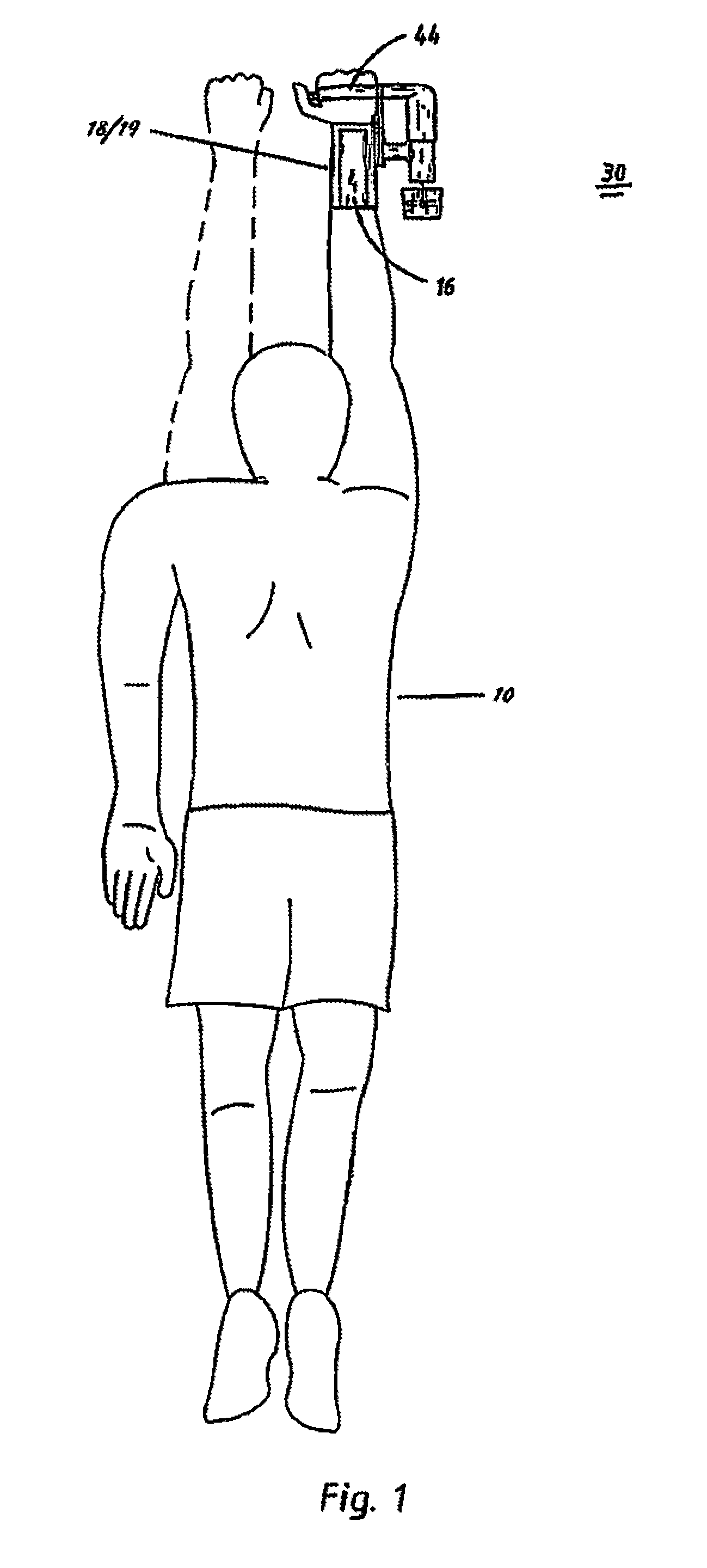
[0025]In the prior art, a swimmer has a tank on his back which is attached to him by a harness. A power unit is typically provided integrally with an impeller unit upon the tank or about a waist and forearm of a swimmer 10.

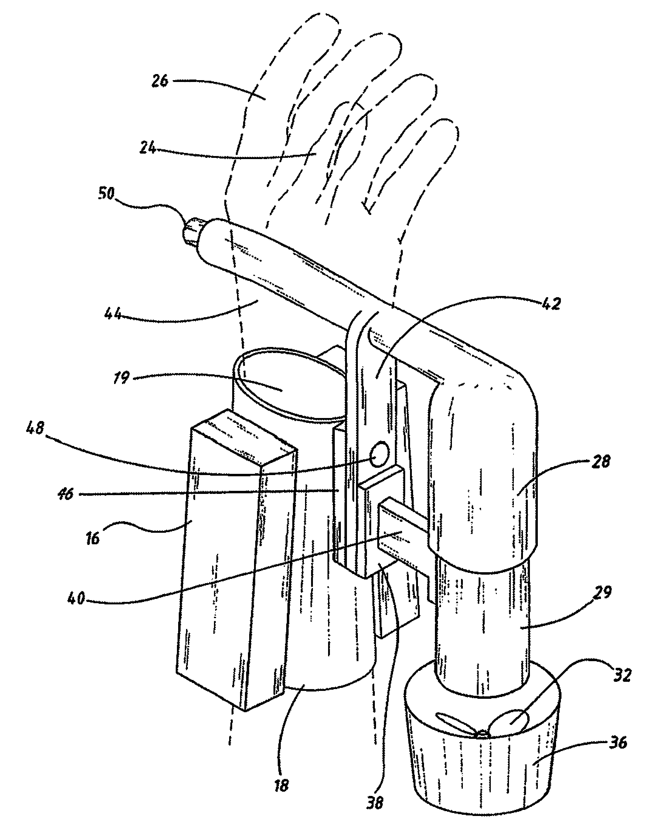
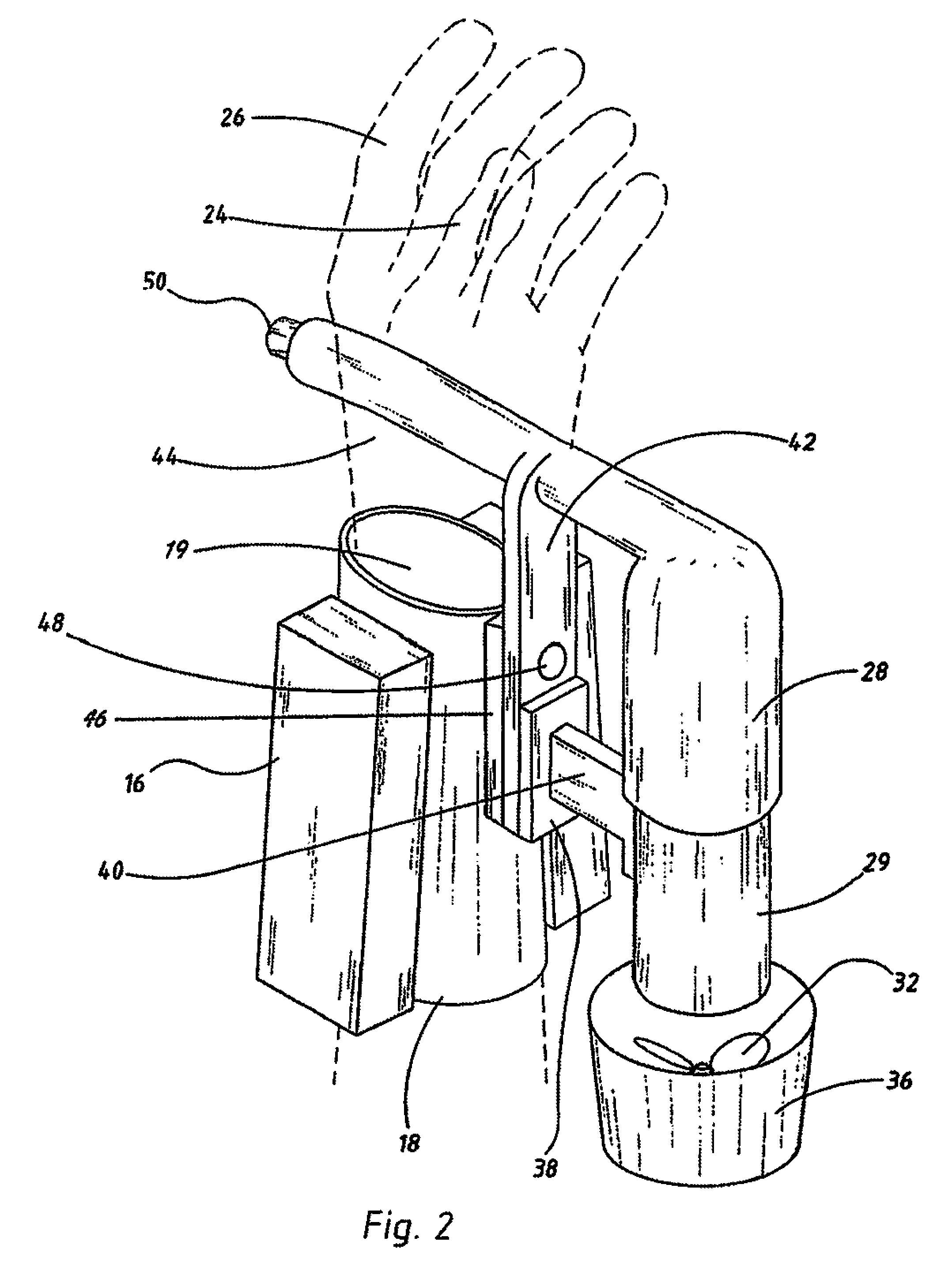
[0026]In the instant invention, two lithium batteries 16 and 16A (see FIG. 3), serve as the power supply of the system preferably connected in series to achieve an output of about 30V DC, and attached to a sleeve 18 or the like, which is typically be an extension of a wet suit of the swimmer 10. Within the sleeve 18 is forearm 19 and wrist 21 of the swimmer 10 from which extends thumb 24 and other fingers 26 of hand 22. The batteries 16 / 16A are in electrical communication with motor power controller 28 (see FIG. 2-4 and electrical block diagram of FIG. 8) which in turn drives a brushless motor 29 and an impeller 32 using a drive shaft 34. The batteries of the system are, as above noted, designed to attach to the sleeve or propulsion unit and can be connected or di...


PUM


Abstract

A propulsion system, for use by a swimmer in both on-water and under-water applications, includes at least one power supply unit attached to a sleeve secured about and to a forearm of the swimmer, at least one corresponding propulsion unit including a motor and an impeller, the propulsion unit offset from the forearm near to the wrist and away from the head of the swimmer, and control elements that actuate the power and propulsion units. One control element includes a grip upon the flexion axis of the swimmer which controls pitch of a longitudinal axis of the propulsion unit relative to a forearm of the swimmer, the control elements include a pivotally secured bracket, and elements for control of the level of power provided to the propulsion unit, in which the rotation and control elements are both positioned for ease of accessibility by a hand of the swimmer.

Description

REFERENCE TO RELATED APPLICATION[0001]This application claims the benefit under 35 USC 119(e) of provisional patent application Ser. No. 61 / 929,300, filed Jan. 20, 2014, which is incorporated by reference in its entirety.BACKGROUND OF THE INVENTION[0002]1. Field of Invention[0003]The instant invention relates to a device for propulsion of a swimmer through the water and, more particularly, to a device and system which is mounted upon the forearm of the swimmer and which may be controlled by the hands and fingers thereof.[0004]2. Prior Art[0005]There is a demand for propulsion units for use by underwater as well as on-water swimmers, inclusive of snorkelers and scuba divers. As such, the term “swimmer” as used herein, includes on-water swimmers, surfers, underwater swimmers, scuba divers, and others. Certain propulsion units are also employed by lifeguards and certain handicapped or disabled persons. There, as well, is a need for improvement in the prior art of such vehicles by the m...

Claims


Application Information

Patent Timeline
Patent Type & Authority Patents(United States)
IPC IPC(8): B63C11/46A63B35/12
CPCA63B35/12
Inventor MELENDEZ, MICHAEL
Owner PROPULSE LLC
Learn More