Stretching device

a technology of stretching device and workpiece, which is applied in the field of rolling or extruding metal and sheet metal or metal plate processing, can solve problems affecting the efficiency or effectiveness of the device, and achieve the effect of preventing damage to the stretched workpiece and reducing slippag

Active Publication Date: 2016-05-03
BUTECH BLISS
View PDF11 Cites 0 Cited by
  • Summary
  • Abstract
  • Description
  • Claims
  • Application Information

AI Technical Summary

Benefits of technology

[0019]Yet another aspect of the disclosure is an extrusion stretcher which has optimized cam style jaws which provide a uniform, reliable gripping force across the full range of extrusion sizes. The stretcher effectively grips the piece and virtually eliminates any slippage.
[0023]In accordance with another aspect of the disclosure, a stretcher assembly has a first stretcher comprising a first housing having a first clamping member and a second clamping member opposed to each other; and a second stretcher comprising a second housing having a third clamping member and a fourth clamping member opposed to each other; a workpiece support member interposed between the first stretcher and the second stretcher; wherein the first and third clamping members each comprise a movable pivot joint such that an angle of contact of the first and third clamping members with a workpiece to be gripped remains constant regardless of a thickness of the workpiece; and each of the first, second, third, and fourth clamping members comprises an insert mounted thereon to protect the workpiece to be gripped.
[0027]Another aspect of the disclosure is that the cam jaws exert a uniform, reliable gripping force on workpieces across a full range of workpiece thicknesses.
[0028]Still another aspect of the disclosure is that the jaw pre-grips the workpiece and virtually eliminates slippage.
[0029]Another aspect of the disclosure is inserts mounted to the stretchers which protect and prevent damage to the workpiece being stretched. Still another aspect of the disclosure is an insert which provides a gripping surface that can protect oiled strip metal as well as dry strip metal.

Problems solved by technology

In previous stretchers, the angle of the cam would change depending on the thickness of the workpiece, thus affecting the efficiency or effectiveness of the device.

Method used


Image

  • Stretching device
  • Stretching device
  • Stretching device

Examples


Embodiment Construction

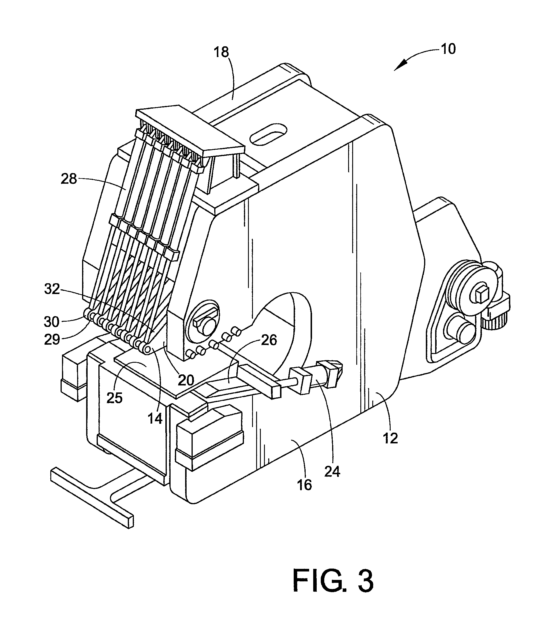
[0053]A method of flattening sheet metal using a stretcher is called “stretcher leveling.” A stretcher, in accordance with the present disclosure is shown in FIGS. 3-14. Stretcher leveling is generally considered to be a superior flattening process because, unlike roller leveling and temper processing, it rectifies the problem of internal residual stresses and produces a flatter product without crown reduction. As shown in FIGS. 3-5, a 350-ton stretching force capacity stretcher includes a “tail stretcher” assembly 10 which has a pivoting cam-style jaw assembly which is shown in an “up” and “down” position in FIGS. 4 and 5. The cam jaw assembly pivots up or retracts into a housing 12.

[0054]FIG. 3 shows a tail stretcher assembly 10 in accordance with a preferred embodiment of the present disclosure. Housing 12 of the tail stretcher assembly supports an upper clamping member or jaw assembly 14 which is mounted securely thereon between opposed parallel side plates 16, 18 of the housing...


PUM

PropertyMeasurementUnit
widthaaaaaaaaaa
distanceaaaaaaaaaa
lengthaaaaaaaaaa

Abstract

A stretching device has a housing, a first clamping member attached to a first portion of the housing, a second clamping member attached to a second portion of the housing, a first insert mounted to the first clamping member, and a second insert mounted to the second clamping member. The first insert and the second insert protect workpieces to be clamped and gripped therebetween. The inserts are releasably mounted to gripping surfaces of the clamping members.

Description

CLAIM OF PRIORITY[0001]This application is a continuation-in-part of application Ser. No. 12 / 483,742, filed on Jun. 12, 2009, which in turn claims priority from Provisional Application No. 61 / 060,999, filed on Jun. 12, 2008. Each application is hereby incorporated herein by reference.BACKGROUND OF THE DISCLOSURE[0002]The present disclosure relates to rolled or extruded metal and sheet metal or metal plate processing. More particularly, the present invention relates to a method and apparatus for stretching extruded or sheet metal using a stretcher machine.[0003]A wide variety of manufactured goods contain processed sheet metal. For example, aircraft, automobiles, file cabinets and household appliances, to name only a few, contain sheet metal. The sheet metal is typically purchased directly from steel mills and / or steel service centers, but may be passed through intermediate processors (sometimes referred to as “toll” processors) before it is received by an original equipment manufact...

Claims


Application Information

Patent Timeline
Patent Type & Authority Patents(United States)
IPC IPC(8): B21D25/04B21D11/02
CPCB21D25/04B21D11/02
Inventor BUTA, JOHN R.MERCER, RYAN CRAIG
Owner BUTECH BLISS
Why Eureka
Try Eureka