
Inkjet printer and printing method using solvent-containing ink

a solvent-containing ink and printer technology, applied in the field of printing apparatus and printing method, can solve the problems of limited irradiation conditions of partially cured ink, difficulty in adequately bringing the partially cured ink to the partially cured state, and difficulty in using inks other than uv curable inks of specific spectral absorption properties, so as to accurately and appropriately print the desired image, appropriately and appropriately suppress the bleeding of ink dots

Active Publication Date: 2016-05-03
MIMAKI ENG
View PDF15 Cites 2 Cited by
  • Summary
  • Abstract
  • Description
  • Claims
  • Application Information

AI Technical Summary

Benefits of technology

[0009]The inventor of the present application conducted intensive studies to find more appropriate ways of transferring an image, and thought of using a solvent-containing ink instead of partially curing a UV curable ink, and performing the transferring after at least partially removing the solvent in the ink. It was found that the transferring can be appropriately achieved without causing problems such as bleeding when the ink has a sufficiently high viscosity after the solvent removal. The present invention can solve the foregoing problems with the following configurations.
[0056]Further, because the bleeding and wrinkling problems are unlikely to occur in the foregoing configuration, a thick ink layer can be formed with sufficient amounts of ink. This makes it possible to sufficiently increase the thickness of the ink layer for higher density printing.

Problems solved by technology

However, the image transfer by such a method requires, for example, accurately controlling the intensity and the duration of the UV irradiation to adequately bring the ink to the partially cured state before the transfer.
Another possible drawback is that the spectral absorption properties of the ink, depending on its relationship with the irradiation wavelength of the UV light used, might limit the irradiation conditions of the partially cured ink, or might pose difficulties in adequately bringing the ink to the partially cured state.
Depending on the irradiation wavelength of the UV light, it might be also difficult to use inks other than UV curable inks of specific spectral absorption properties.
The overcuring of the ink dot surface may lower the adhesion of the dot surface, and the ink may not be properly transferred to a medium.
Conversely, the ink dots may not be sufficiently cured inside by partial curing to make the ink dot surface suitable for transfer.
This may result in ink transfer failure, or may cause ink bleeding after the transfer.
In the foregoing image transfer method, therefore, partial curing of the ink may not be performed properly for adequate image transfer.
That is, it may not be possible with the foregoing method to appropriately perform image transfer printing.
Further, because removing the organic solvent in the ink does not cure the ink, the ink viscosity can sufficiently increase upon sufficiently removing the organic solvent.
The heating member may heat the transfer image forming member at a temperature that does not cure the binder resin in the ink on the transfer image forming member.
However, such a method may fail to perform accurate printing with known inks.
For example, when a common solvent ink is used, the ink bleeds when its ink droplets are directly ejected onto a paper medium.
Direct printing of a paper medium with a solvent ink is therefore difficult.
Direct printing with an aqueous ink is therefore not always suitable for common paper media (such as a plain paper).
Such uncured monomers (residual monomers) are often undesirable in terms of their effect on the environment and users.
Direct printing with a UV curable ink may produce ink dots that are noticeably granular, and may fail to appropriately produce glossy prints.
Indeed, direct printing of a paper medium with a UV curable ink is not always suitable.
The problems of medium wrinkling and residual monomers are also unlikely to occur.
Further, because the bleeding and wrinkling problems are unlikely to occur in the foregoing configuration, a thick ink layer can be formed with sufficient amounts of ink.

Method used


Image

  • Inkjet printer and printing method using solvent-containing ink
  • Inkjet printer and printing method using solvent-containing ink
  • Inkjet printer and printing method using solvent-containing ink

Examples


Embodiment Construction

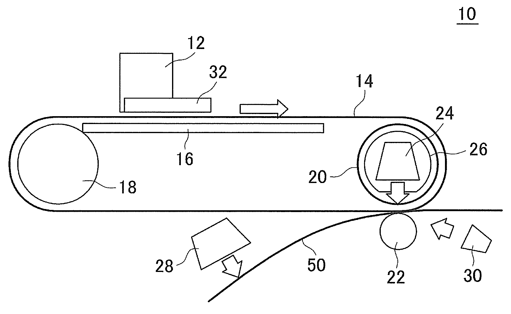
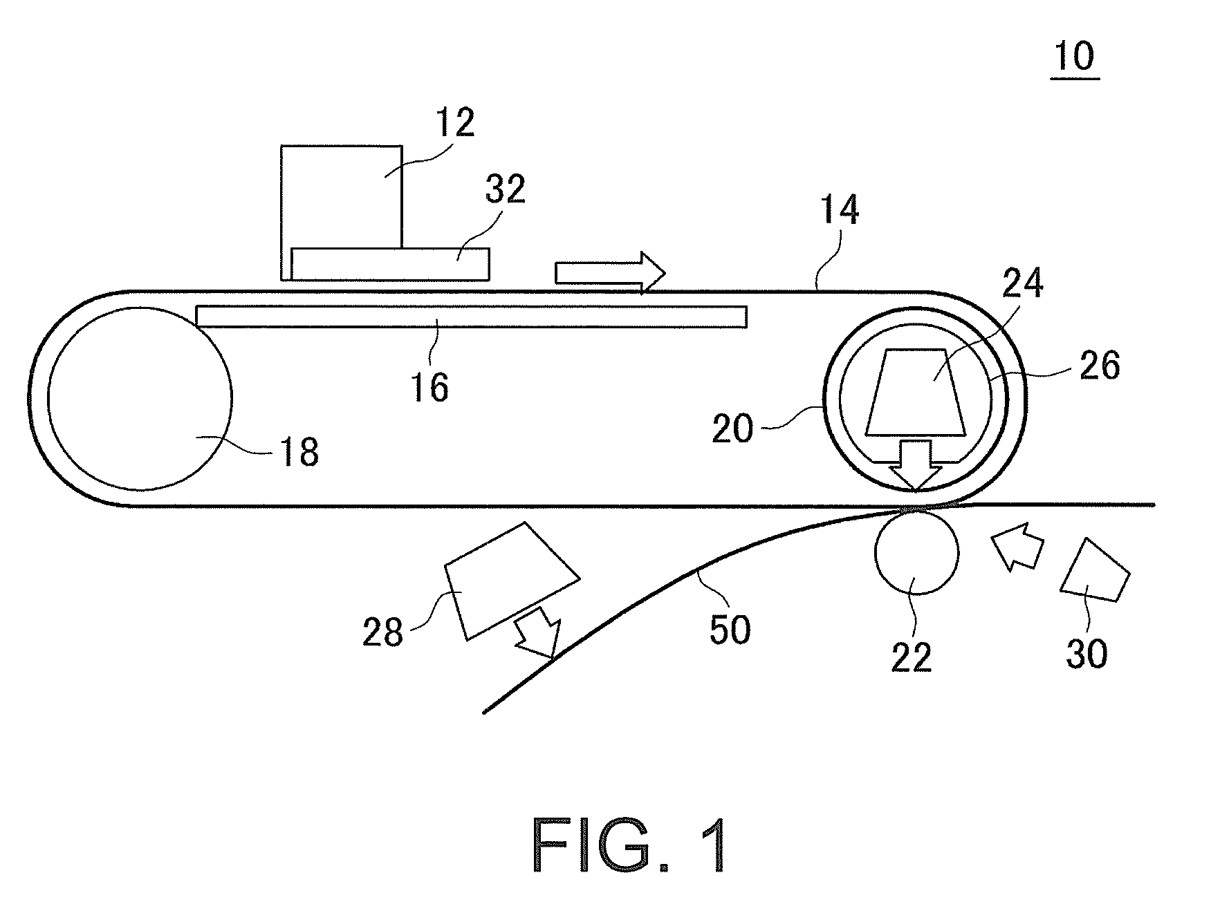
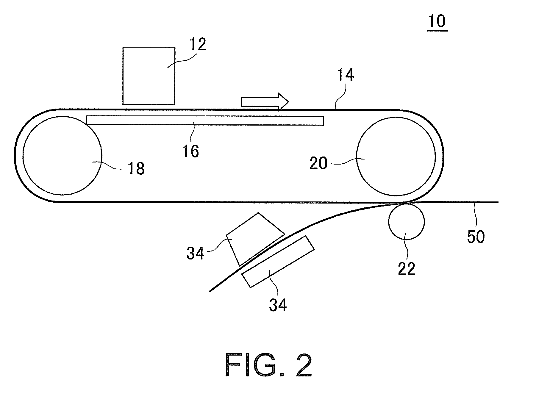
[0065]Embodiments of the present invention are described below with reference to the accompanying drawings. FIG. 1 represents a first exemplary configuration of a printing apparatus 10 according to an embodiment of the present invention. The printing apparatus 10 is a printing apparatus that performs an image transfer printing. For example, the printing apparatus 10 prints a medium 50, for example, such as a paper, using an image transfer printing. Here, “printing” means, for example, forming an image (such as characters and graphic patterns) on the medium 50. The printing apparatus 10 also can be deemed as an image forming apparatus that forms an image on the medium 50 by using a digital offset printing.

[0066]The medium 50 is, for example, a plain paper. The medium 50 may be, for example, a paper without an ink receptive layer. The medium 50 also may be a non-paper medium. For example, the medium 50 may be any of various media made from materials such as a plastic, resin, and metal...


PUM


Abstract

The invention provides ways of appropriately performing image transfer printing. A printing apparatus for performing image transfer printing is provided that includes: a transfer belt provided as a transfer image forming member on which a transfer image is created; an inkjet head that creates the transfer image on the transfer belt; a counter heater provided as a heating member that heats the transfer belt; a transfer roller provided as a transfer member that transfers the transfer image to a medium; and a strong UV irradiator provided as an image fixing unit that fixes to the medium the image transferred to the medium. The inkjet head ejects ink droplets of an ink containing a solvent that is removed by heating with the counter heater. The ink has a viscosity of 50 mPa·sec or more after the solvent is removed by heating with the counter heater.

Description

CROSS-REFERENCE TO RELATED APPLICATION[0001]This application claims the priority benefit of Japan application serial no. 2013-115162, filed on May 31, 2013. The entirety of the above-mentioned patent application is hereby incorporated by reference herein and made a part of this specification.BACKGROUND[0002]1. Technical Field[0003]The present invention relates to a printing apparatus, and a printing method.[0004]2. Description of Background Art[0005]An image forming apparatus, in which an image formed on an intermediate transfer rotating medium is transferred to a recording medium to achieve printing (see, for example, JP-A-2007-112117), is known. In the configuration disclosed in JP-A-2007-112117, an image is formed on an intermediate transfer rotating medium with a UV curable ink having predetermined spectral absorption properties, and the ink is brought to a partially cured state by irradiation of a UV light of a predetermined wavelength. The image formed by the partially cured i...

Claims


Application Information

Patent Timeline
Patent Type & Authority Patents(United States)
IPC IPC(8): B41J2/01
CPCB41J2/01B41J2002/012
Inventor OHNISHI, MASARU
Owner MIMAKI ENG
Learn More