Processor for electronic endoscope and electronic endoscope apparatus

a technology of electronic endoscope and processor, which is applied in the field of processor for electronic endoscope and electronic endoscope apparatus, can solve the problems of extended diagnostic time, and achieve the effect of reliably obtaining the desired still image in a short period of tim

Active Publication Date: 2016-05-10
HOYA CORP
View PDF39 Cites 891 Cited by
  • Summary
  • Abstract
  • Description
  • Claims
  • Application Information

AI Technical Summary

Benefits of technology

[0008]The present invention is made to solve the above described problem. That is, the objection of the invention is to provide a processor for an electronic endoscope and an electronic endoscope apparatus capable of reliably obtaining a desired still image in a short period of time.
[0024]As described above, according to the invention, a processor for an electronic endo scope and an electronic endo scope apparatus capable of reliably obtaining a desired still image in a short period of time are realized.

Problems solved by technology

However, in the configuration of the patent document 1, the obtained still image having a lower level of blur or color drift does not always correspond to a desired still image, and therefore there is a case where re-obtaining of a still image is needed.
Therefore, when obtaining of a still image is required again, it is necessary to wait until image data is stored in the memory again, which causes a problem that a diagnosis time extends.

Method used


Image

  • Processor for electronic endoscope and electronic endoscope apparatus
  • Processor for electronic endoscope and electronic endoscope apparatus

Examples


first embodiment

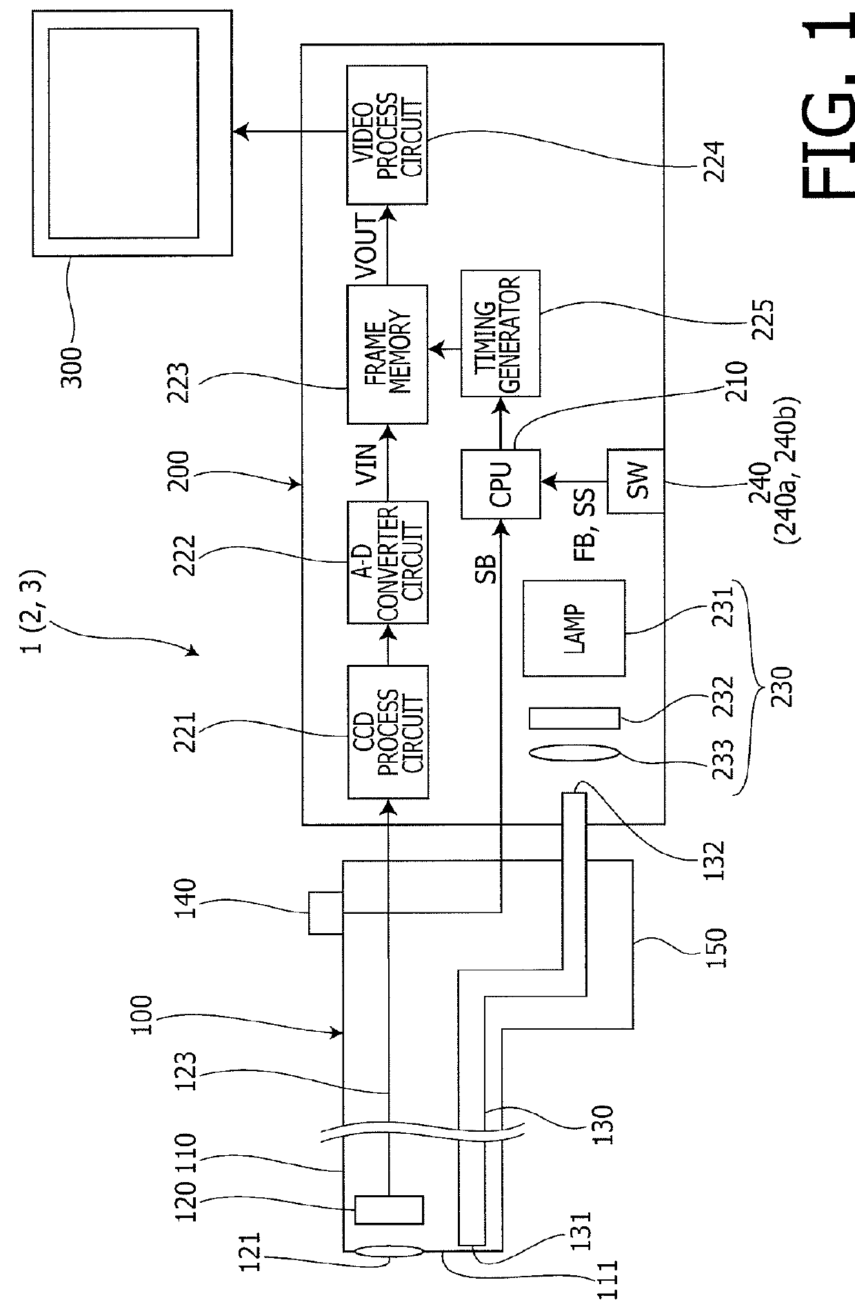
[0032]An electronic endoscope apparatus 1 according to a first embodiment of the invention is explained with reference to FIGS. 1 to 4. FIG. 1 is a block diagram of the electronic endoscope apparatus 1 according to the first embodiment of the invention. The electronic endoscope apparatus 1 according to the embodiment includes an electronic endoscope 100, a processor 200 for the electronic endoscope, and a monitor 300.

[0033]An objective lens 121 and an image pick-up device 120 are accommodated in the vicinity of a tip portion (an insertion tube tip part) 111 in an insertion tube 110 of the electronic endoscope 100. The objective lens 121 converges a subject image near to the insertion tube tip part 111 onto a light receiving surface of the image pick-up device 120.

[0034]The image pick-up device 120 outputs an image signal corresponding to the image converged onto the light receiving surface. The image signal is transmitted to a CCD process circuit 221 of the processor 200 for the ele...

second embodiment

[0062]Next, an electronic endoscope apparatus 2 according to a second embodiment of the invention is explained with reference to FIG. 5. The electronic endoscope apparatus 2 according to the second embodiment of the invention has the same configuration as the electronic endoscope apparatus 1 according to the first embodiment shown in FIGS. 1 and 2, and is different from the first embodiment only in regard to the image recording / reproducing operation. In the following, the different point from the first embodiment is explained in detail.

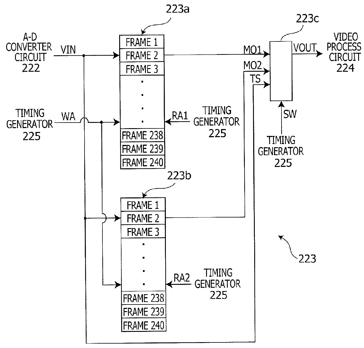
[0063]FIG. 5 is a timing chart illustrating the image recording / reproducing operation executed by the electronic endoscope apparatus 2 according to the second embodiment of the invention. The image recording / reproducing operation according to the second embodiment is different from the image recording / reproducing operation according to the first embodiment shown in FIG. 3 in that the same image data on the first memory 223a and the second memory 223b ...

third embodiment

[0067]Next, an electronic endoscope apparatus 3 according to a third embodiment of the invention is explained with reference to FIG. 6. The electronic endoscope apparatus 3 according to the third embodiment of the invention has the same configuration as the electronic endoscope apparatus 1 according to the first embodiment shown in FIGS. 1 and 2, and is different from the first embodiment only in regard to the image recording / reproducing operation. In the following, the different point from the first embodiment is explained in detail.

[0068]FIG. 6 is a timing chart illustrating the image recording / reproducing operation executed by the electronic endoscope apparatus 3 according to the third embodiment of the invention. The third embodiment is different from the image recording / reproduction operation of the electronic endoscope apparatus 1 according to the first embodiment shown in FIG. 3 in that the first rewind reproduction process and the second rewind reproduction process are not p...


PUM


Abstract

A processor for an electronic endoscope includes first and second image storing units and a controller, which in a first mode, image data is converted sequentially into a video signal and is outputted while being stored sequentially in the first and second image storing units. In a second mode, image data stored in the first image storing unit is outputted while generated image data is sequentially stored in the second image storing unit. In a third mode, image data stored in the second image storing unit is outputted while generated image data is sequentially stored in the first image storing unit. In the second and third modes, it is possible to switch between a first playback mode that continuously outputs the multiple stored image data and a second playback mode that repeatedly outputs one of the multiple stored image data.

Description

TECHNICAL FIELD[0001]The present invention relates a processor for an electronic endoscope which processes an image signal from an electronic endoscope and displays video, for example, on a monitor, and an electronic endoscope apparatus including the above described electronic endoscope and the processor.BACKGROUND ART[0002]Electronic endoscope apparatuses have been widely used for observation and diagnosis for a body cavity. The electronic endoscope apparatus includes an image pick-up device at its tip portion, and includes an electronic endoscope which outputs an image signal of an image shot by the image pick-up device, and a processor for the electronic endoscope which processes the image signal from the electronic endoscope, converts the image signal into a video signal having a predetermined format (e.g., a video signal in NTSC format) and displays the video, for example, on a monitor.[0003]Generally, the processor for the electronic endo scope displays the image picked up by ...

Claims


Application Information

Patent Timeline
Patent Type & Authority Patents(United States)
IPC IPC(8): A61B1/00H04N7/18H04N1/46G02B23/24A61B1/05A61B5/00H04N5/232H04N5/225A61B1/04A61B1/045
CPCA61B1/00009A61B1/0002A61B1/0005A61B1/00006A61B1/042A61B1/045A61B1/05A61B5/0031G02B23/2476H04N5/23232H04N7/183H04N2005/2255H04N23/555H04N23/951
Inventor OZAWA, RYO
Owner HOYA CORP
Why Eureka
Try Eureka