Inverter terminal block installed in motor case

a terminal block and motor case technology, applied in the field of suitable, can solve problems such as damage to the connection of the connection device, and achieve the effect of ensuring the water-proof properties of the terminal block

Active Publication Date: 2016-05-17
YAZAKI CORP
View PDF51 Cites 22 Cited by
  • Summary
  • Abstract
  • Description
  • Claims
  • Application Information

AI Technical Summary

Benefits of technology

[0026]While a conventional terminal block constructs the inverter side connecting terminal and the motor side connecting terminal by the integral terminal block, according to the first invention as described above, the upper base for accommodating the inverter side connecting terminal is separated from the lower base for accommodating the motor side connecting terminal in the terminal block and the elastic member is interposed between the upper base and the lower base, so that vibration of the motor side becomes resistant to propagating to the inverter side and moreover, the terminal block resistant to vibration can be obtained by connecting the motor side connecting terminal to the inverter side connecting terminal by the flexible conductive member.
[0027]Further, since the elastic member interposed between the upper base and the lower base is provided with waterproof properties, even if a vehicle is submerged in water and the water enters a gap between the motor case and the inverter case, the water can be prevented from entering the inside of the terminal block from a fitted part of the upper base and the lower base by the waterproof and elastic member.
[0028]According to the second and third inventions of the present application, the waterproof rubber stoppers are interposed between the upper base and the inverter case and between the lower base and the motor case, respectively, so that waterproof properties of the terminal block are ensured more.

Problems solved by technology

However, in such a configuration, a vibration phase difference between the inverter and the motor by vibration of the motor itself or vibration of a vehicle body at the time of driving is applied to a connector and the connector may be damaged.

Method used


Image

  • Inverter terminal block installed in motor case
  • Inverter terminal block installed in motor case
  • Inverter terminal block installed in motor case

Examples


Embodiment Construction

[0033]A terminal block of the invention with good waterproof and oilproof properties, capable of sufficiently exerting a sealing effect on vibration even when strong vibration occurs between a motor side connecting terminal and an inverter side connecting terminal and variations due to assembly tolerances of a motor and an inverter are great will hereinafter be described based on the drawings.

[0034]

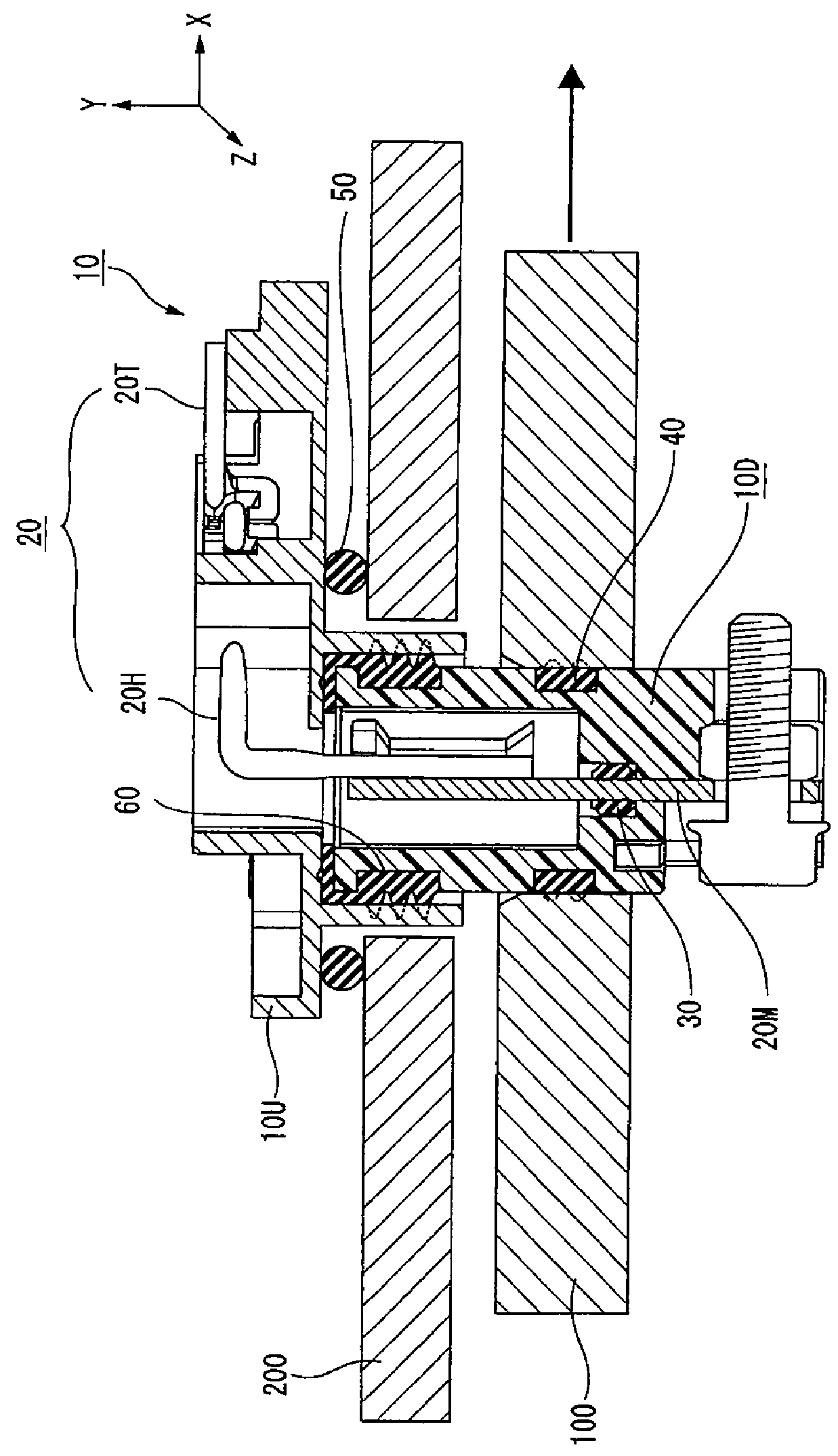
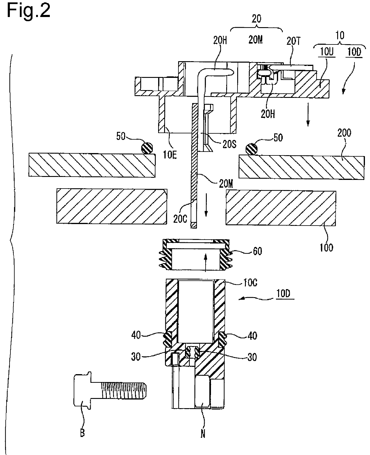
[0035]In FIG. 1 showing a longitudinal section of a terminal block according to the invention and FIG. 2 exploding and showing the terminal block of FIG. 1, numeral 100 is a motor case and numeral 200 is an inverter case placed in the motor case 100.

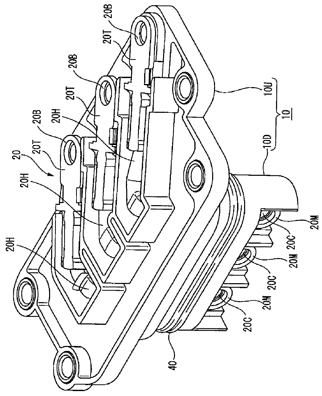
[0036]Numeral 10 is a terminal block according to the invention interposed between the motor case 100 and the inverter case 200. The terminal block 10 is a container molded of resin, and is means for receiving three-system electric conductors 20 (an inverter side connecting terminal 20T, a braided wire 20H and a motor side connecting terminal ...


PUM


Abstract

In a terminal block 10 which is interposed between a motor case 100 and an inverter case 200 placed in the motor case 100 and connects a motor input terminal to an inverter output terminal, an upper base 10U for accommodating an inverter side connecting terminal 20T connected to the inverter output terminal is fixed to the inverter case 200, and a lower base 10D for accommodating a motor side connecting terminal 20M is fixed to the motor case 100, and a waterproof and elastic member 60 is interposed between the upper base 10U and the lower base 10D and the motor side connecting terminal 20M is connected to the inverter side connecting terminal 20T by a flexible conductive member (a braided wire) 20H.

Description

TECHNICAL FIELD[0001]The present invention relates to a suitable inverter terminal block unaffected by vibration under an environment of occurrence of the vibration in the case of installing an inverter used for a vehicle etc. in a motor case.BACKGROUND ART[0002]An electric vehicle or a hybrid electric vehicle generally includes a motor and an inverter between a battery and wheels in order to drive the wheels by electric power accumulated in the battery.[0003]The electric power accumulated in the battery is converted by the inverter of an inverter device etc. and is supplied to the motor and rotates the motor, and rotation of the motor is transmitted to the wheels and drives the wheels.[0004]Conventionally, the inverter and the motor were mounted in separate places of the vehicle and a terminal of the inverter was connected to a terminal of the motor using a wire harness.[0005]On the other hand, a structure of integrating an inverter with a motor for the purpose of cost reduction an...

Claims


Application Information

Patent Timeline
Patent Type & Authority Patents(United States)
IPC IPC(8): H02K5/22H01R13/52H01R4/34H01R13/74H02K5/24H01R4/18
CPCH02K5/225H01R13/5202H01R4/183H01R4/34H01R13/74H01R2201/26H02K5/24H02K11/33H02K3/28H02K11/0094
Inventor OKAMOTO, KENICHIKOBAYASHI, MASAKI
Owner YAZAKI CORP
Why Eureka
Try Eureka