Precision liquid applicator

a liquid applicator and precision technology, applied in the field of liquid dispensers, can solve the problems that none of the aforementioned liquid dispensers were capable of dispensing paint to a very small surface without, and achieve the effect of minimizing the application of paint and minimizing the application of liquid

Active Publication Date: 2016-05-24
FLOCON
View PDF48 Cites 3 Cited by
  • Summary
  • Abstract
  • Description
  • Claims
  • Application Information

AI Technical Summary

Benefits of technology

[0059]The valve stop cooperates with the stop wall to establish a desired a cross-sectional area of the passageway between the precision applicator tip and the terminal orifice upon total depression of the precision applicator tip. A dimension of one of the valve stop and the stop wall is selected relative to a viscosity of the applicator liquid for establishing a desired a cross-sectional area of the passageway between the precision applicator tip and the terminal orifice to provide a desired flow of the applicator liquid to the precision applicator tip. The valve stop cooperates with a stop wall for limiting movement of the valve to control a cross-sectional area of the passageway between the precision applicator tip and the terminal orifice for controlling the flow of the applicator liquid to minimize the application of the applicator liquid to areas adjacent to the intended area of application on the surface.
[0060]The invention is also incorporated into a precision liquid applicator for dispensing a paint liquid from a container onto a scratch in a painted surface. The precision liquid applicator comprises a closure secured to the container. The closure has an internal closure orifice defining a terminal orifice with a sealing seat adjacent to the terminal orifice. A valve having a precision applicator tip with a valve seal is located adjacent to the precision applicator tip. A biasing spring urges the valve seal of the valve into engagement with the sealing seat of the closure for inhibiting the flow of the paint from the terminal orifice. A depression of the precision applicator tip onto the scratch of the paint surface displaces the valve seal from the sealing surface for providing an annular passageway between the precision applicator tip and the terminal orifice to enable the flow of the paint into the scratch in the paint surface. A valve stop is located on the valve cooperating with a stop wall for limiting movement of the valve to control a cross-sectional area of the passageway between the precision applicator tip and the terminal orifice for controlling the flow of the paint and for ensuring the precision applicator tip extends beyond the second end of the closure to minimize the application of the paint to areas adjacent to the scratch in the paint surface.

Problems solved by technology

Although the above patents and patent applications have contributed substantially to the art, none of the aforementioned liquid dispensers were capable of dispensing an applicator liquid such as paint to a very small surface without dispersing the applicator liquid to an adjacent area.

Method used


Image

  • Precision liquid applicator
  • Precision liquid applicator
  • Precision liquid applicator

Examples


Embodiment Construction

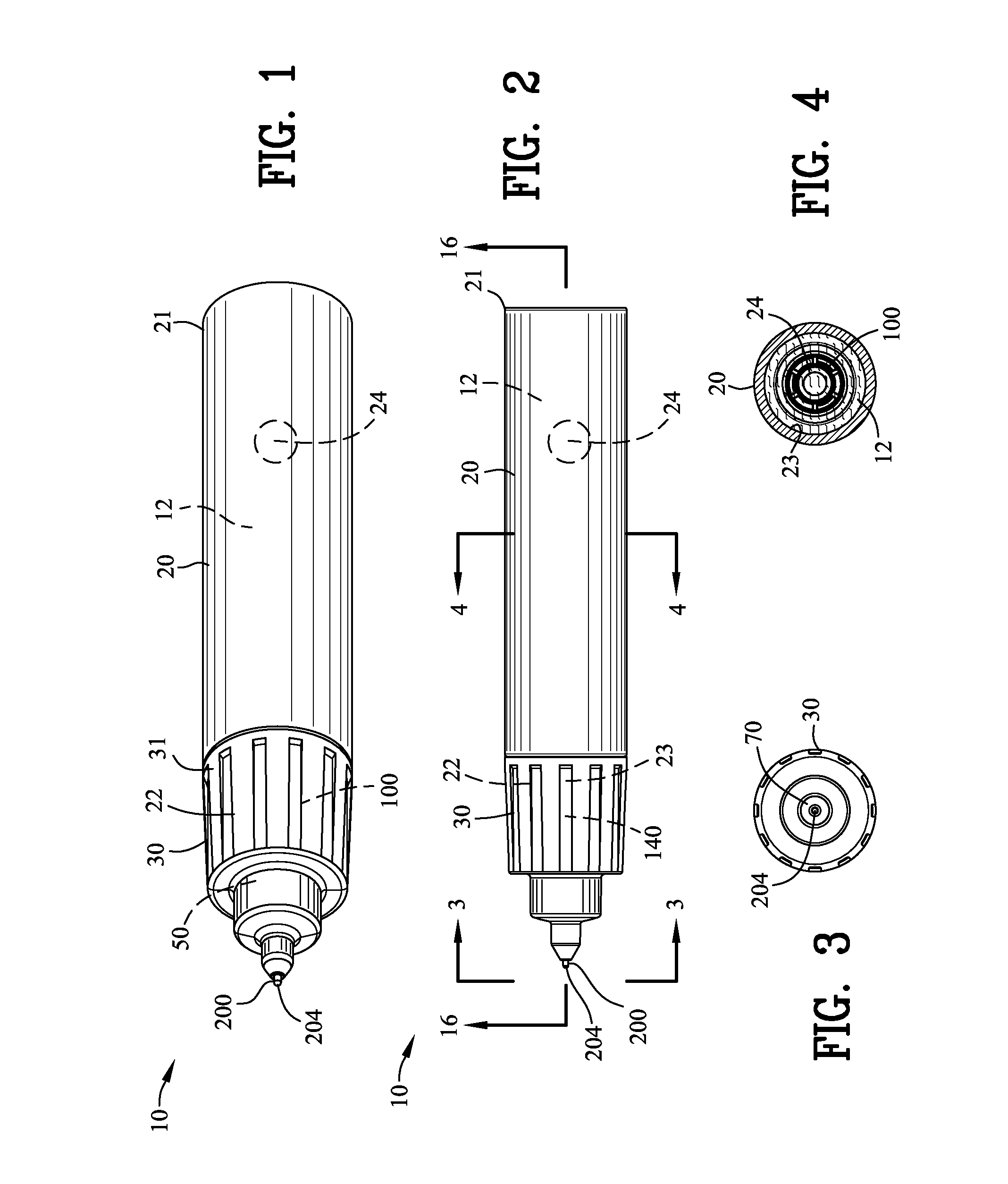
[0103]FIGS. 1-4 are various views of the precision liquid applicator 10 for dispensing an applicator liquid 12 from a container 20. The container extends between a first end 21 and the second end 22. The first end 21 of the container is closed in a conventional manner where as the second end 22 is an open end as indicated by 23 for providing liquid flow from the container 20 and the precision liquid applicator 10.

[0104]The container 20 is shown as a metallic container but it should be appreciated that the container 20 may be formed of other materials such as glass or polymeric materials. In addition, the shape of the container 20 forms no part of the present invention. An optional agitator 24 may be incorporate within the container 20 for a mixing the applicator liquid 12 in the event such mixing is required for a specific applicator liquid 12 used with the precision liquid applicator 10.

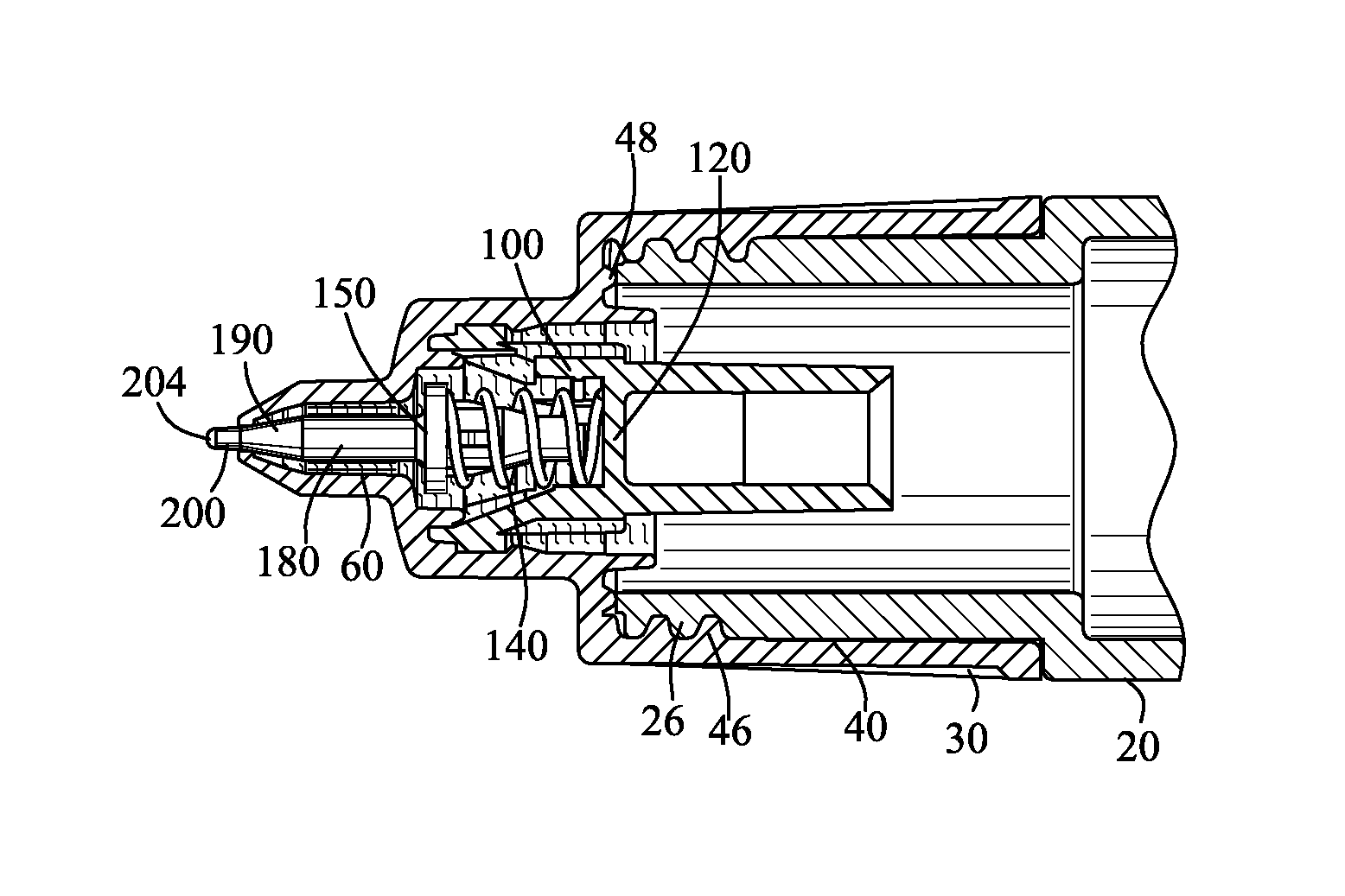
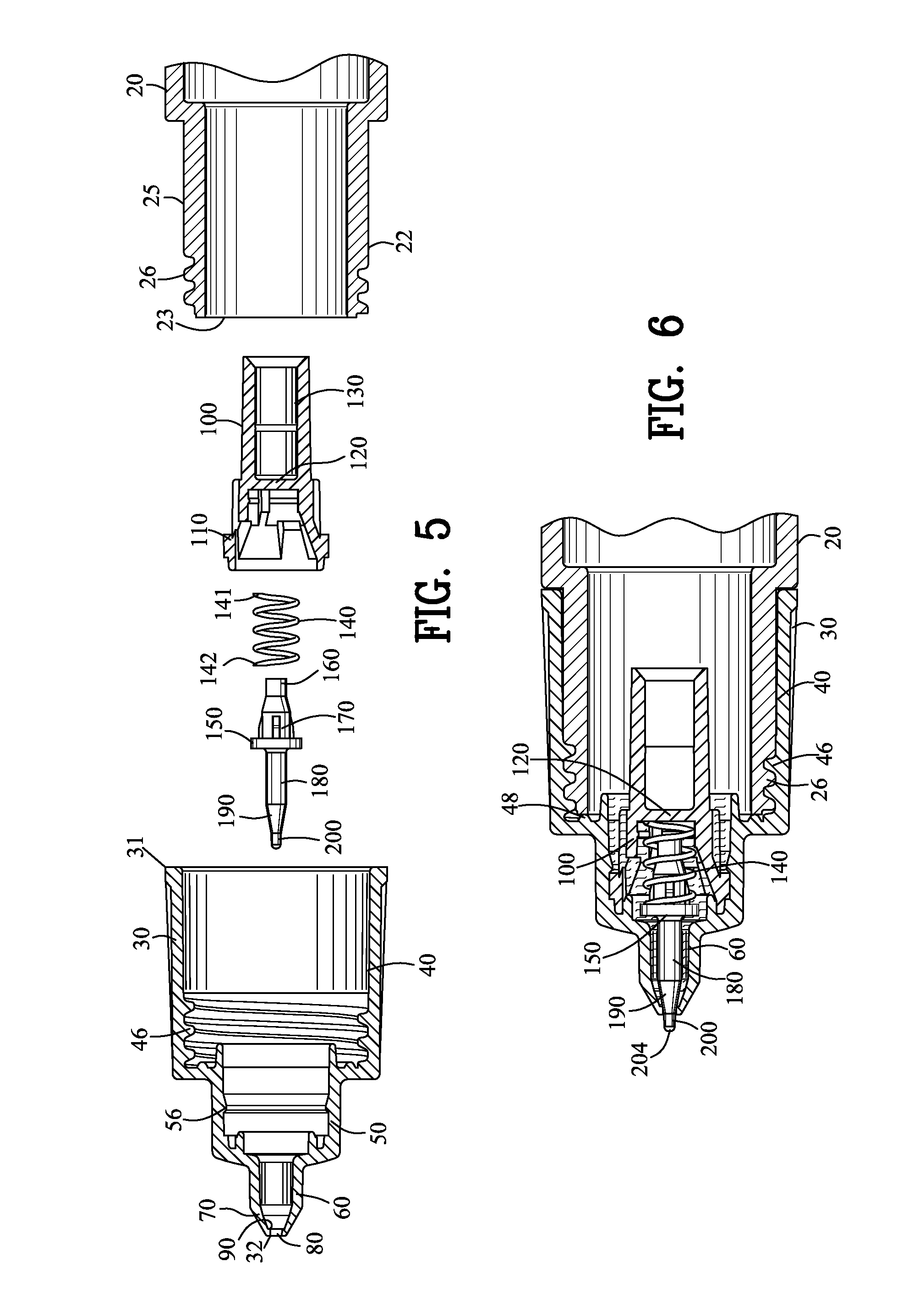
[0105]FIGS. 5 and 6 are enlarged exploded and assembled views of the precision liquid applicator...


PUM


Abstract

A precision liquid applicator is disclosed for dispensing an applicator liquid from a container onto a surface. The precision liquid applicator comprises a closure defining a terminal orifice and a valve seat. A valve comprises a precision applicator tip extending through the terminal orifice and comprises a valve seal for sealing with the valve seat. A depression of the precision applicator tip onto the surface displaces the valve seal from the sealing surface for providing an annular passageway between the precision applicator tip and the terminal orifice to enable the flow of the applicator liquid onto the surface. A valve stop cooperates with a stop wall for limiting movement of the valve to control a cross-sectional area of the passageway between the precision applicator tip and the terminal orifice and for ensuring the precision applicator tip extends beyond the second end of the closure. The precision liquid applicator is suitable for applying paint into a scratch within a painted surface without excessive application of paint outside of the scratch.

Description

CROSS-REFERENCE TO RELATED APPLICATIONS[0001]This application claims benefit of U.S. Patent Provisional application No. 61 / 611,811 filed 16 Mar. 2012. All subject matter set forth in provisional application No. 61 / 611,811 filed 16 Mar. 2012 is hereby incorporated by reference into the present application as if fully set forth herein.BACKGROUND OF THE INVENTION[0002]1. Field of the Invention[0003]This invention relates to dispensing of liquids and more particularly, this invention relates to a precision liquid applicator for dispensing a liquid on or into a small surface such as a scratch or defect in a paint surface.[0004]2. Description of the Related Art[0005]Various types of liquid applicator devices have been devised for dispensing a liquid. Some of these liquid applicator devices were used for dispensing an applicator liquid for writing with ink, dye or paint. Among such devices were fountain pens, ball point pens, felt tip pens as well as other types of liquid applicator device...

Claims


Application Information

Patent Timeline
Patent Type & Authority Patents(United States)
IPC IPC(8): B43K5/17B05C17/00B05C1/00B43K5/18A45D34/04B05D5/00
CPCB05C1/00A45D34/042A45D34/045B05C17/00B43K5/1836B43K5/1845B05D5/005
Inventor BALLOT, STEPHAN M
Owner FLOCON
Why Eureka
Try Eureka