Pipe and tubes cleaning mechanism

a cleaning mechanism and pipe technology, applied in the field of cleaning systems and methods, can solve the problems of reducing the internal capacity of reservoirs and pipes, reducing fluid discharge, and increasing friction of the internal surfaces of pipes and tubes

Inactive Publication Date: 2016-05-24
KHANI MOGHANAKI MEHDI
View PDF8 Cites 3 Cited by
  • Summary
  • Abstract
  • Description
  • Claims
  • Application Information

AI Technical Summary

Benefits of technology

[0010]The primary object of the embodiments herein is to provide an improved cleaning mechanism for cleaning steady / curved half or completely-blocked pipes / tubes.
[0011]Another object of the embodiments herein is provide a cleaning mechanism based on the structure and transfer mechanism of lubricant liquid to minimize blockage on the course of liquid transfer to a cleaning tool.
[0012]Yet another object of the embodiments herein is to provide a cleaning mechanism which eliminates damage of the internal body of pipes / tubes.

Problems solved by technology

The purpose of cleaning tanks, pipes / tubes and valves that are places for storing or passing residual fluids is fundamental as the changing level of internal section of the pipes and reservoirs is followed by frequent harmful and undesirable consequences such as reduced internal capacity of reservoirs and pipes, reduction in fluid discharges of and increased friction of the internal surfaces of the pipes and tubes.
However the use of such methods results in blockage of the course of the liquid and subsequent sedimentation after a while.
The use of chemical materials generally harms the applied equipment and gradually looses their efficiency.
Also these physical methods are not advisable in case of liquids without or with minimum sedimentary materials such as polymer and petroleum fluids.
However these methods have potential drawbacks.
Faults / defects of these methods include impossibility of direct defurring / cleaning completely or half blocked pipes with bends thereby causing probable damage of pipes and water jets with higher pressure.
Also these methods are not flexible for the existence of rigid pipes / tubes transmitting force, the breakage of drill and damage of internal casing of pipe / tubes are more likely during the smashing of stiff / hard or elastic sediments.
In the meantime, as the size of water vents is too small, the vents are immediately blocked with the increased volume of sediment so that the increased in the friction and the thermal tension at the tip of means contributes to the breaking speed of the drill and damages the pipes / tubes.
Since the kinetic force system could not be controlled, a small conflict, occurred at the tip of the cleaning drill with sediment, imposes a considerable tension to the tip of the instrument and causes breaking of the the tip leaving it inside the pipe / tubes, thereby distorting the defurring / cleaning function.
Moreover, these tools are by no means applicable in case of half-blocked and completely-blocked pipes / tubes, hard and dendrite sediments.

Method used


Image

  • Pipe and tubes cleaning mechanism
  • Pipe and tubes cleaning mechanism
  • Pipe and tubes cleaning mechanism

Examples


Embodiment Construction

[0031]In the following detailed description, reference is made to the accompanying drawings that form a part hereof, and in which the specific embodiments that may be practiced is shown by way of illustration. These embodiments are described in sufficient detail to enable those skilled in the art to practice the embodiments and it is to be understood that the logical, mechanical and other changes may be made without departing from the scope of the embodiments. The following detailed description is therefore not to be taken in a limiting sense.

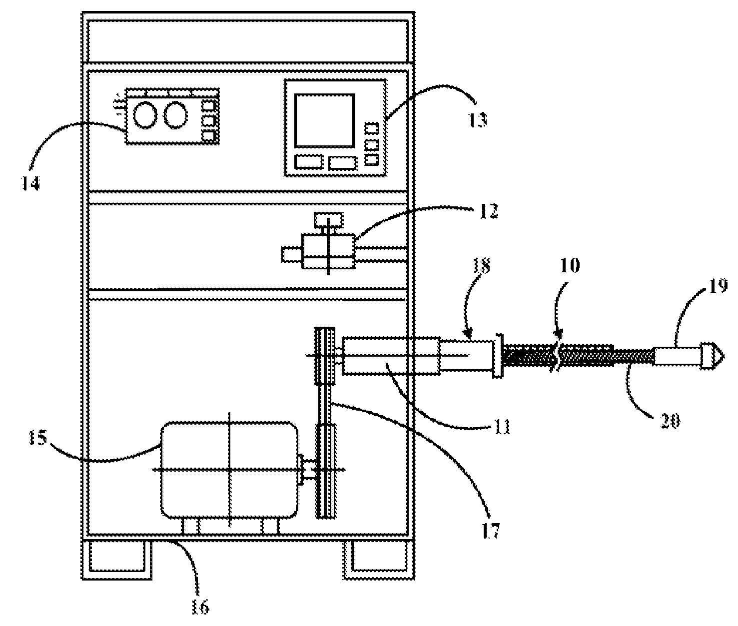
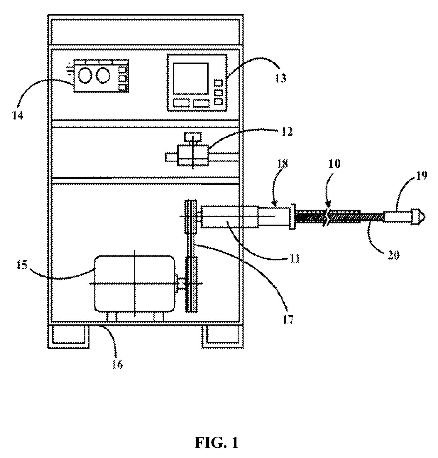
[0032]The various embodiments herein provide a cleaning system for removing sediments or blocks from inaccessible surfaces like interiors of pipes / tubes or channels blocked by sediments or other deposits. The cleaning system, according to the embodiment herein, is preferably used for cleaning industrial pipes / tubes and oil industry equipments blocked by sediments. The cleaning system uses a power transfer shaft and by transferring a kinetic for...


PUM


Abstract

The various embodiments herein provide a mechanism for cleaning the interior surfaces of pipes / tubes. The mechanism comprises a power transfer shaft, a power generator, a power transmission means attached to the power generation means and the power transfer shaft, an electrical valve and pump, an electrical unit to generate a dynamic force, a controller for remote force controlling, a liquid guidance system integrated to the power transfer shaft, a movement conditioner for the power transfer shaft; and at least one cleaning tool removably attached to the power transfer shaft. The at least one cleaning tool includes a predefined structure to convert a turning movement of the cleaning tool into a rotational movement of the power transfer shaft for cleaning of the deposits in the pipe / tubes without any damage to an internal body of the pipe & tube.

Description

BACKGROUND[0001]1. Technical Field[0002]The embodiments herein generally relates to cleaning systems and methods and more particularly relates to cleaning / de-furring systems to remove residues from inaccessible surfaces such as interior of pipes / tubes.[0003]2. Description of the Related Art[0004]Industrial units are invariably concerned with the issue of maintenance of equipments and machineries. Generally, the maintenance activities are launched with a purpose to enhance the output and performance of the machinery and / or to mitigate risk of probable damages as well as to increase shelf life of operating machinery.[0005]The purpose of cleaning tanks, pipes / tubes and valves that are places for storing or passing residual fluids is fundamental as the changing level of internal section of the pipes and reservoirs is followed by frequent harmful and undesirable consequences such as reduced internal capacity of reservoirs and pipes, reduction in fluid discharges of and increased friction...

Claims


Application Information

Patent Timeline
Patent Type & Authority Patents(United States)
IPC IPC(8): F28G3/00E03F9/00B08B9/045F28G3/04F28G3/16F28G3/10
CPCB08B9/045E03F9/005F28G3/04F28G3/10F28G3/16
Inventor KHANI MOGHANAKI, MEHDI
Owner KHANI MOGHANAKI MEHDI
Why Eureka
Try Eureka