Coating substrates with an alloy by means of cathode sputtering

a cathode sputtering and alloy technology, applied in the direction of electrolysis components, vacuum evaporation coatings, coatings, etc., can solve the problems of high cost of methods, difficult to determine the optimum composition of alloys for sputtering targets, and change in alloy composition during sputtering

Active Publication Date: 2016-05-24
SINGULUS TECHNOLGIES AG
View PDF22 Cites 7 Cited by
  • Summary
  • Abstract
  • Description
  • Claims
  • Application Information

AI Technical Summary

Benefits of technology

[0019]According to the invention, the plasma can also have a circular or elliptical cross-section so that the erosion section is accordingly formed as a circle or ellipse. By moving the plasma transversely with respect to the target boundary line, the alloy composition on the coated substrate is changed. If it is intended to form a layer from an alloy with more than two materials, it is possible to arrange the sections of different materials in different manners on the target surface. For example, the sections of the different materials can be arranged in a star-shaped manner on the target surface. By moving the circular or elliptic erosion section relative to such a star-shaped arrangement parallel with respect to the surface of the target, the respective amounts of the materials forming the alloy can be freely selected.
[0025]For achieving that the boundary line between the two sections extends at an acute angle α relative to the direction of the erosion section, the sections of the surface of the target can be trapezoidal, wherein these trapezoidal sections are arranged such that strips of different materials are formed on the surface of the rectangular target, the boundary lines of these strips being tilted relative to the longitudinal side of the target by an angle. In a typically structured device for large-area cathode sputtering and in particular for magnetron cathode sputtering with a long cathode, a race track-shaped erosion section is formed on the target, wherein two elongate trenches are formed in the longitudinal direction of the target. For these two trenches, a homogeneous transition between the materials should be realized. Therefore, preferably three trapezoidal sections are provided. It is thus possible to achieve a structure in which the boundaries between the sections of different materials extend at an acute angle α relative to the direction of the straight sections of the race track-shaped erosion section, so that at one end more material of the one section and at the other end more material of the other section is removed. In case of a relative movement of the substrate substantially perpendicular with respect to the longitudinal direction of the long cathode, a corresponding different alloy composition is obtained in the transverse direction of the substrate.

Problems solved by technology

It is a further problem—mainly in case materials having clearly different atomic masses are used—that during cathode sputtering the alloy composition can change during the deposition.
Since in the end the composition of the alloy on the substrate is important, it is often difficult to determine the optimum composition of the alloy of the sputtering target.
This method is very costly, in particular in case expensive materials (PtMn, FePt, etc.) are used.
In these series tests, the corresponding targets must be inserted in and removed from the corresponding vacuum systems, which is very time-consuming.
Mainly when using relatively large substrates it is difficult in connection with this technology to produce a homogeneous alloy on the substrate and at the same time achieve a homogeneous layer thickness.
Therefore, this method is restricted to a limited number of materials—also among the metals.

Method used


Image

  • Coating substrates with an alloy by means of cathode sputtering
  • Coating substrates with an alloy by means of cathode sputtering
  • Coating substrates with an alloy by means of cathode sputtering

Examples


Embodiment Construction

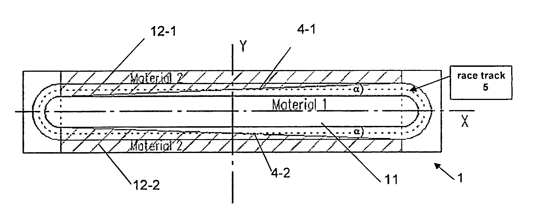
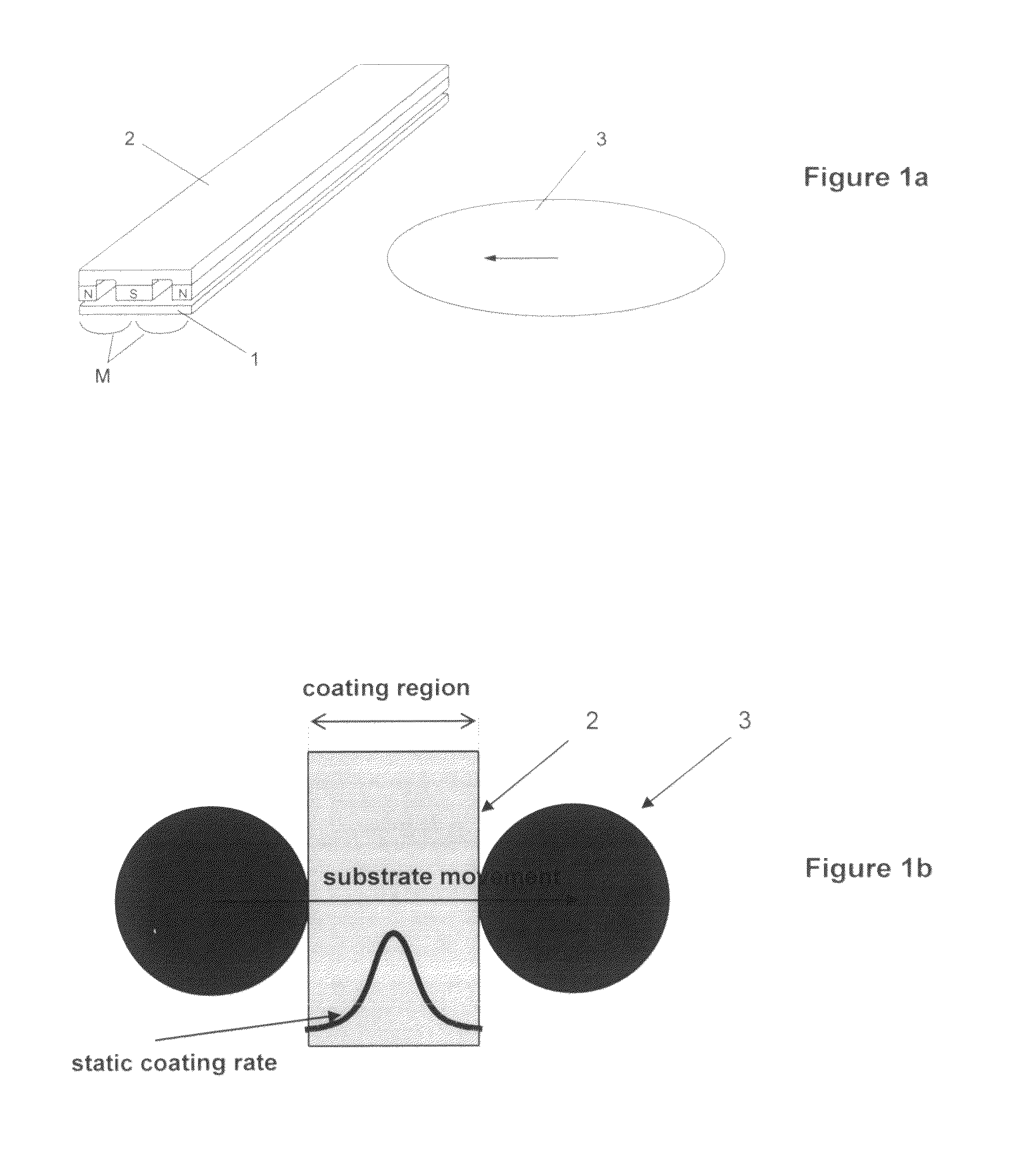
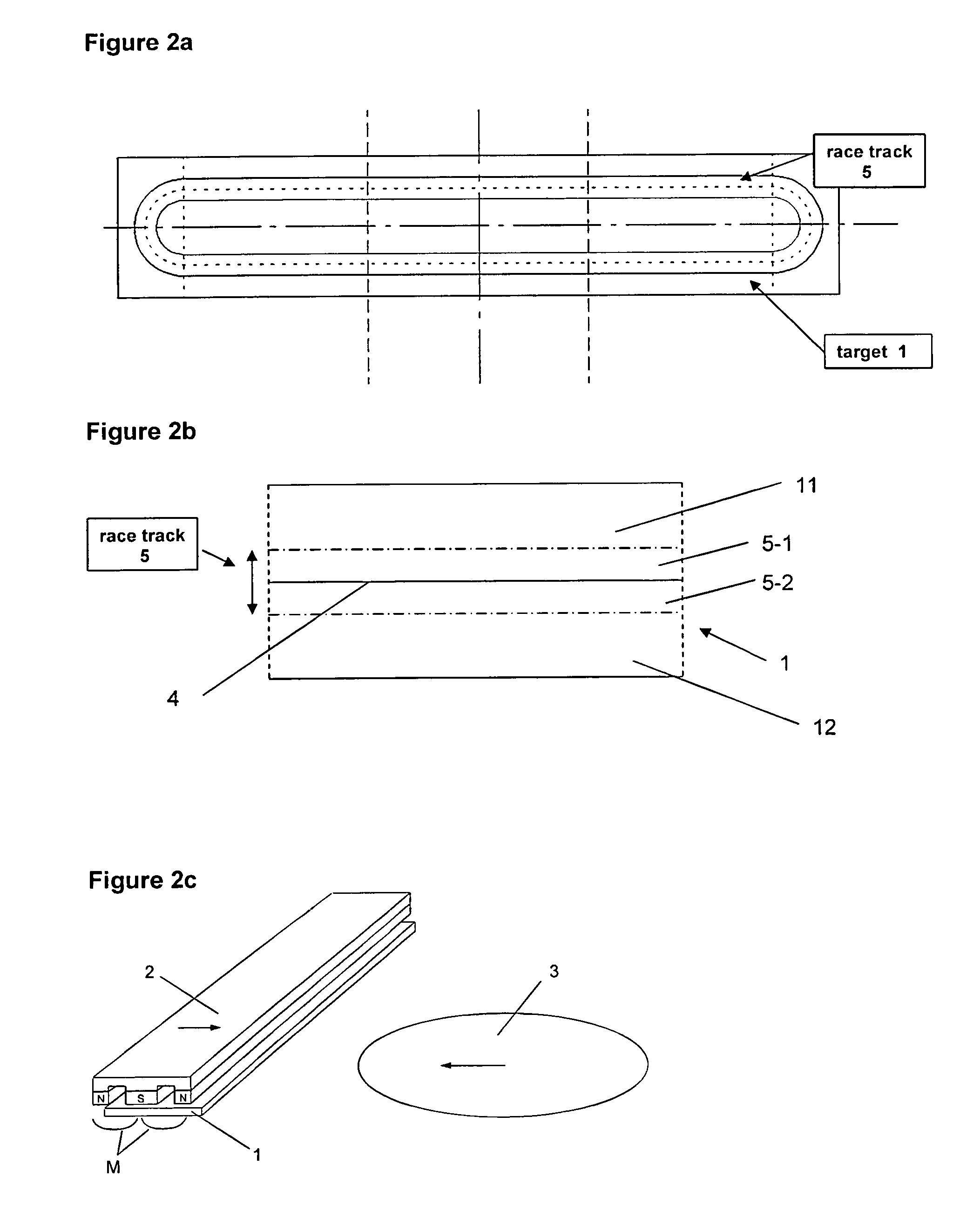
[0043]The present invention is based on the so-called linear dynamic deposition (LDD) technology as used, e.g., also in coating systems of the type TIMARIS of Singulus Technologies AG. The basic principle used therein is known, e.g., from WO 03 / 071579 already cited above. FIG. 1 schematically shows a structure of a corresponding cathode sputtering system which can also be used in accordance with the present invention. The device in the form of a long cathode comprises a long target 1 and an accordingly elongate magnetron magnet arrangement 2 arranged thereon. The magnet arrangement 2 with magnetic poles N-S-N generates a magnetic field, which is shown in FIG. 1a by the magnetic field lines M indicated below the target 1. A layer of the material of target 1 can be applied to a substrate 3 being arranged below the target 1 when viewed from the direction of the magnetic field arrangement. FIG. 1b illustrates in a top view the static coating rate achieved under the target 1 in a coating...


PUM

PropertyMeasurementUnit
widthaaaaaaaaaa
lengthaaaaaaaaaa
areaaaaaaaaaaa

Abstract

The invention relates to a target for coating a substrate with an alloy by means of cathode sputtering, said alloy having at least one first material and one second material as alloy components. The surface of the target has at least one first section made of the first material and one second section made of the second material. The two sections adjoin each other and form a common boundary line. The invention further relates to a device and a method for coating a substrate with an alloy by means of cathode sputtering using the target according to the invention.

Description

[0001]This Patent Application is a U.S. National Phase Patent Application from PCT Application No. PCT / EP2011 / 066895, filed Sep. 28, 2011 and claiming priority from German Patent Application No. 102010046780.4 filed Sep. 28, 2010.FIELD OF THE INVENTION[0002]The present invention relates to the production of thin layers on a substrate by means of cathode sputtering, in particular magnetron cathode sputtering. The present invention particularly relates to the coating of a substrate with an alloy having a defined alloy composition and / or a defined change in the alloy composition across the surface of the substrate, i.e. a defined concentration gradient which comprises materials of the alloy.BACKGROUND TO THE INVENTION[0003]A method and a device for coating a substrate by means of cathode sputtering is known, e.g., from WO 03 / 071579. Said document discloses a sputtering cathode by means of which a coating of a substrate can be produced in particular by using magnetic and / or magnetizable...

Claims


Application Information

Patent Timeline
Patent Type & Authority Patents(United States)
IPC IPC(8): C23C14/35H01J37/34C23C14/34
CPCC23C14/35C23C14/3407H01J37/3405H01J37/3429H01J37/34
Inventor MAASS, WOLFRAMOCKER, BERTHOLDLANGER, JURGEN
Owner SINGULUS TECHNOLGIES AG
Why Eureka
Try Eureka