Method and arrangement for controlling the lubrication of a gear system

a gear system and lubrication technology, applied in the direction of gearing details, mechanical equipment, machines/engines, etc., can solve the problems of difficult to find the proper lubrication method, and achieve the effect of easy integration, easy scaling of the lubrication control method, and control of the lubrication

Active Publication Date: 2016-05-31
MOVENTAS GEARS
View PDF17 Cites 3 Cited by
  • Summary
  • Abstract
  • Description
  • Claims
  • Application Information

AI Technical Summary

Benefits of technology

[0008]An objective of the present invention is to provide a method and an arrangement for controlling the lubrication of a gear in an effective and advantageous way. Another objective of the present invention is to ensure that control of the lubrication can be achieved with reasonable investment in machinery and instrumentation. A further objective of the invention is to ensure that lubrication control can be easily integrated with other control functionalities of a gear unit. Yet another objective of the invention is to enable easily scaling the lubrication control method to gears of various dimensions.
[0013]The viscosity of typical lubrication fluids is inversely proportional to their temperature. An increasing internal temperature of the gear, where the lubrication fluid comes into contact with the moving mechanical parts, causes the lubrication fluid to warm up. Consequently the viscosity of the lubrication fluid decreases, and the capability of the lubrication fluid to maintain a lubricating film between contacting metal parts gets weaker. Also the flow resistance observed in the lubrication channels decreases. The latter would tend to lower the pressure reading, unless there is feedback from the pressure measurement to the controlled output power of the lubrication pump.

Problems solved by technology

Concerning a wind turbine, which may stand still for lengthy periods, such an axis driven lubrication pump would cause a delay at startup before a sufficient amount of lubrication fluid could reach the critical moving parts, and is thus not to be recommended.
However, even in such cases finding the proper lubrication method is not straightforward.

Method used


Image

  • Method and arrangement for controlling the lubrication of a gear system
  • Method and arrangement for controlling the lubrication of a gear system
  • Method and arrangement for controlling the lubrication of a gear system

Examples


Embodiment Construction

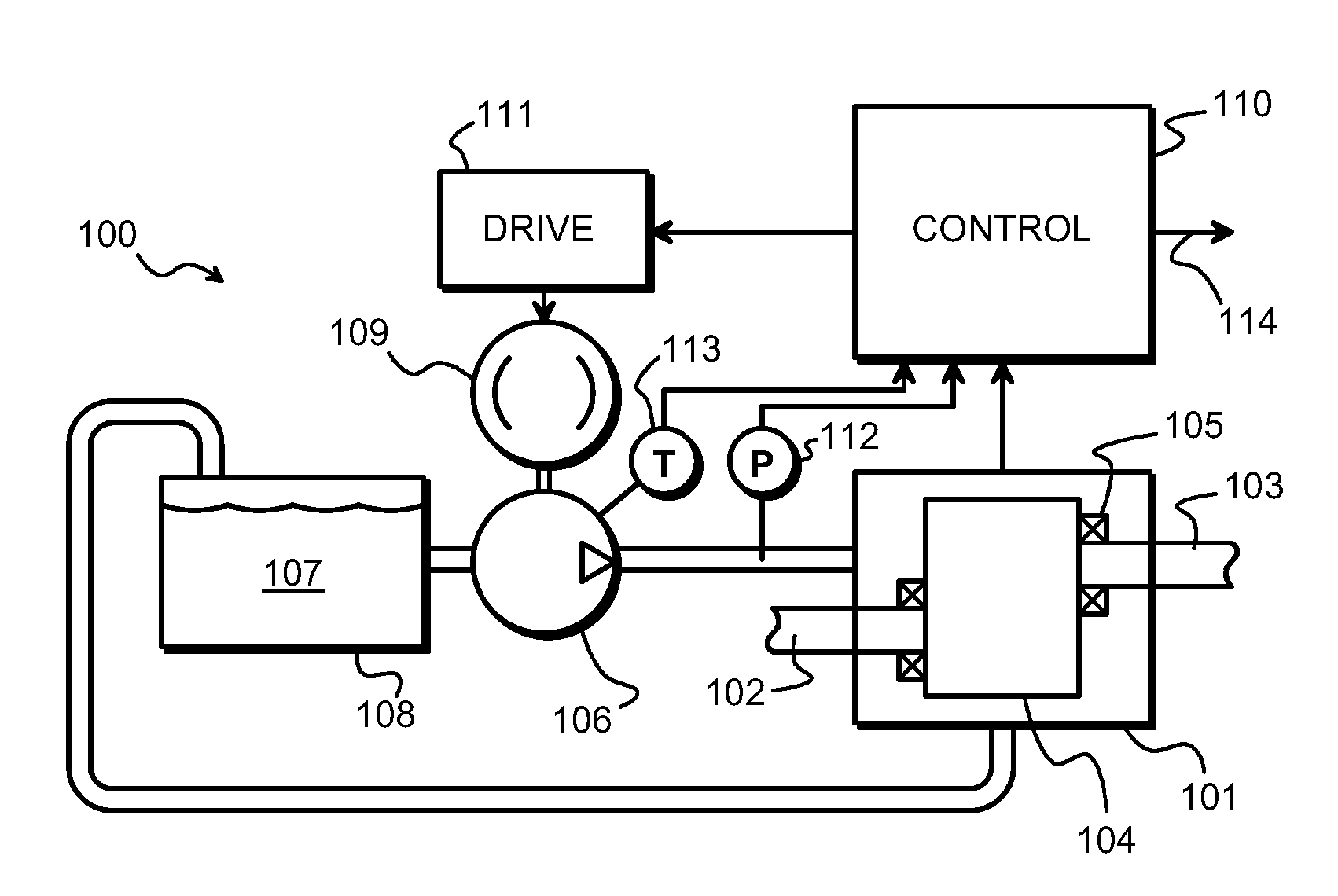
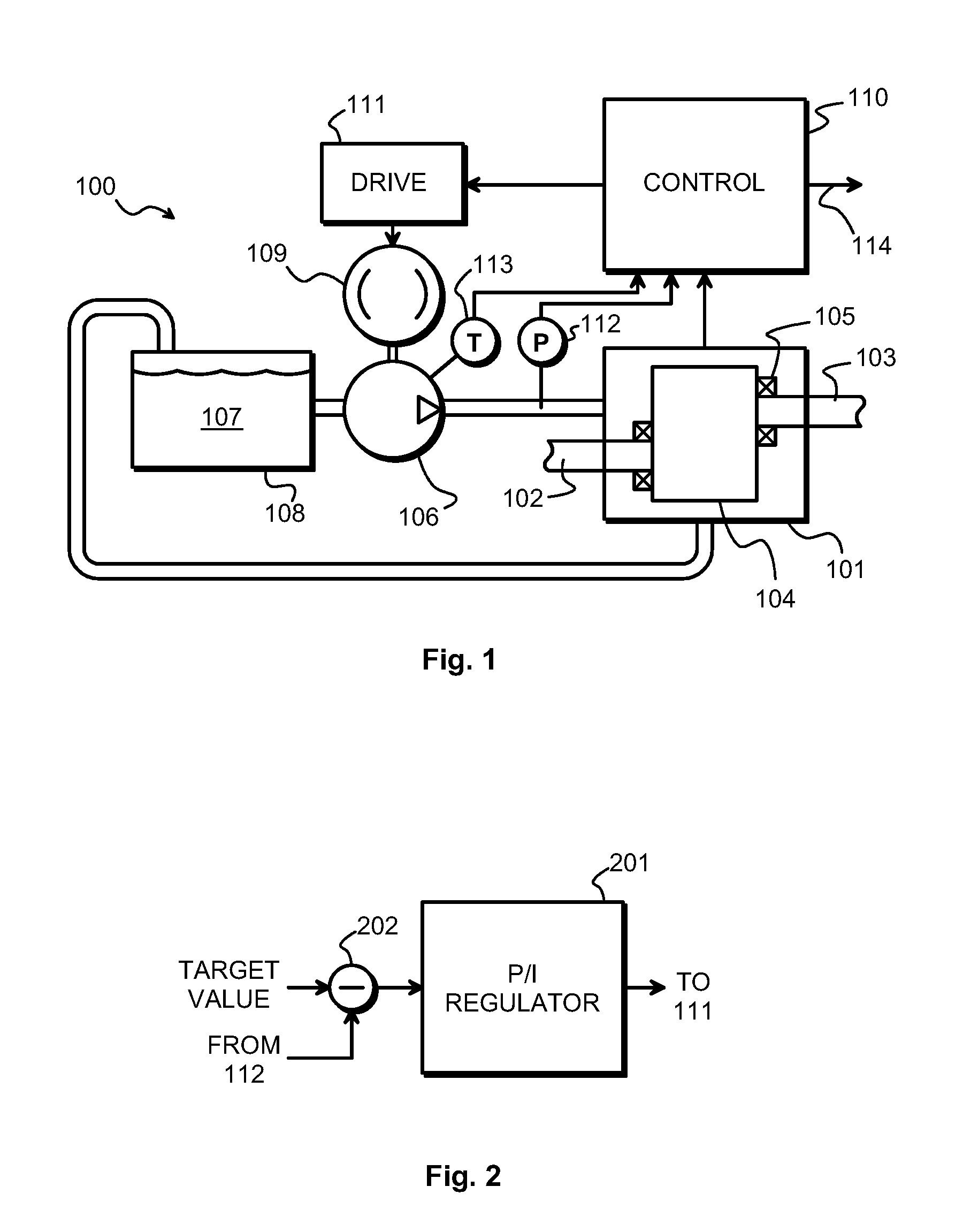
[0023]FIG. 1 is a schematic illustration of certain parts of a gear unit 100, such as a gear unit for a wind turbine. A gear 101 comprises a first shaft 102 and a second shaft 103 for connecting to an external mechanical system, such as a rotor and a generator respectively. Within the gear 101 at least one gear stage 104 is located between the first and second shafts 102 and 103. The shafts are supported with bearings, of which bearing 105 is shown as an example.

[0024]In addition to the gear proper the gear unit comprises a gear lubrication arrangement. A part of the gear lubrication arrangement is a lubrication pump 106 for circulating lubrication fluid, such as lubrication oil 107 that is schematically shown to come from an oil sump or reservoir 108. The use of a reservoir is specific to so-called dry sump solutions, in which there is no large-capacity oil sump directly underneath the lubricated machine parts. The present invention has been designed specifically for dry sump gears...


PUM


Abstract

A gear lubrication arrangement comprises a lubrication pump for circulating lubrication fluid. A power source coupled to the lubrication pump drives the lubrication pump, and a controller controls an output power of the lubrication pump. The gear lubrication arrangement comprises a pressure sensor disposed down-stream of the lubrication pump The pressure sensor is configured to measure a pressure of the lubrication fluid and to produce a pressure indication signal representative thereof. The controller is arranged to vary the output power of the lubrication pump at least partly on the basis of the pressure indication signal.

Description

TECHNICAL FIELD[0001]The invention concerns in general the technology of providing lubrication to a mechanical gear. Especially the invention concerns the technology of ensuring proper lubrication under a wide variety of conditions, over which an operator responsible for correct operation of the gear may have little or no influence.BACKGROUND OF THE INVENTION[0002]In this description we use the term gearwheel to refer to a cogged, rotating machine part. Two or more meshing gearwheels constitute a gear stage. The term gear as such refers in this description to a mechanical system having a first shaft and a second shaft, between which one or more gear stages provide speed and torque conversions and / or a change in a direction of a rotational axis. A gear unit comprises a gear proper and may comprise auxiliary augmenting systems, such as instrumentation, control, and lubrication arrangements.[0003]The gear unit of a wind turbine plays an important part in transmitting the power and the ...

Claims


Application Information

Patent Timeline
Patent Type & Authority Patents(United States)
IPC IPC(8): F16H57/04F16N1/00
CPCF16H57/0435Y10T74/19991Y02E10/72F03D80/70F16H61/4165
Inventor UUSITALO, KARIELFSTROM, JUKKA
Owner MOVENTAS GEARS
Why Eureka
Try Eureka