Seal assembly with complementary surface deformations

a surface deformation and sealing technology, applied in the direction of engine sealing, endless track vehicles, vehicles, etc., can solve the problems of extreme wear of earth moving machines, agricultural and construction applications,

Active Publication Date: 2016-05-31
CATERPILLAR INC
View PDF18 Cites 5 Cited by
  • Summary
  • Abstract
  • Description
  • Claims
  • Application Information

AI Technical Summary

Benefits of technology

[0006]With any of the aforementioned types of seal assemblies it is important for the load ring to maintain contact with the seal ring so as to accomplish all of the foregoing objectives, i.e., biasing the seal ring toward the pin, limiting outflow of lubricant, and preventing inflow of debris. Accordingly, it has been known to provide a number of different configurations for maintaining contact between the load ring and seal ring such as providing splines on one or both of the load ring and seal ring. In so doing, rotational translation between the two components is hopefully avoided. However, continuous improvement in such seal assemblies is always being sought and it is desirable to provide such a seal assembly which accomplishes all the foregoing objectives, while at the same time even further limiting the movement of the load ring relative to the seal ring in all directions.

Problems solved by technology

Machines used in earth moving, agricultural and construction applications are subjected to extreme wear.

Method used


Image

  • Seal assembly with complementary surface deformations
  • Seal assembly with complementary surface deformations
  • Seal assembly with complementary surface deformations

Examples


Embodiment Construction

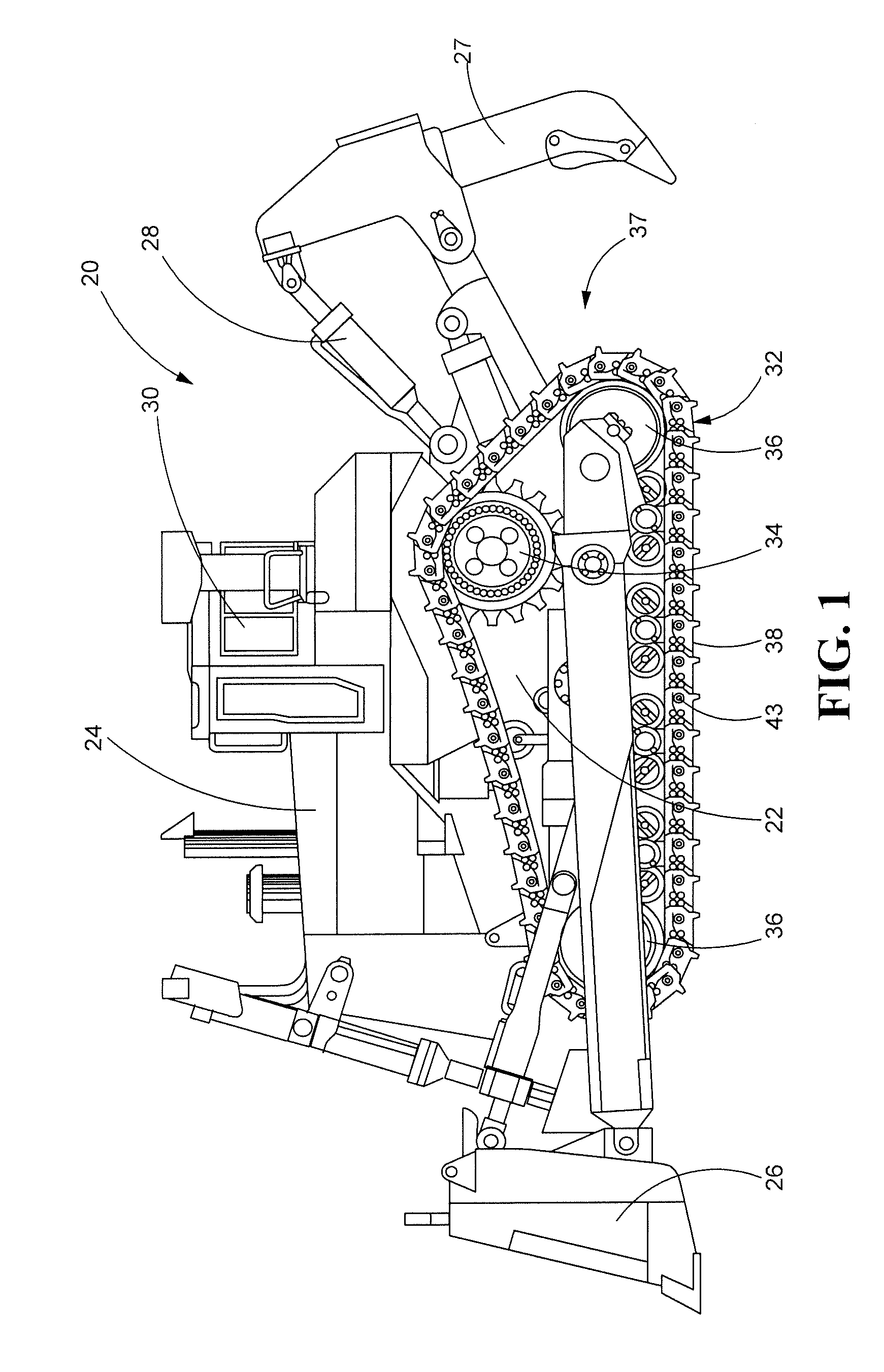
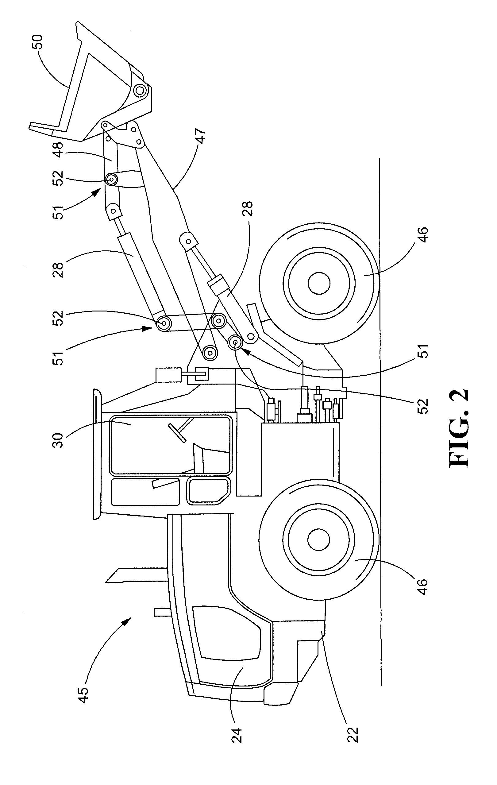
[0023]Turning now to the drawings, and with specific reference to FIG. 1, a machine constructed in accordance with the teachings of the disclosure is generally referred to by reference numeral 20. While machine 20 is depicted as a track-type tractor having bulldozing and ripping capabilities, it is to be understood that the teachings of the disclosure are not so limited but rather can be employed in any number of different machines including but not limited to track-type tractors, loaders (wheeled and tracked), motor graders, pipe layers, excavators, mining equipment or miners, paving equipment or pavers, and trucks.

[0024]Turning again to FIG. 1, the machine 20 is shown to include a chassis 22 which is mounted on an engine 24. Typically, the engine 24 is a diesel engine, but any number of other types of engines and prime movers including but not limited to Otto cycle internal combustion engines and electric motors are possible. The machine 20 further includes a blade 26 for performi...


PUM


Abstract

A seal assembly is disclosed which may include a seal ring, a load ring in engagement with the seal ring, and complementary surface deformations in the seal ring and load ring, the complementary surface deformations circumscribing the seal ring and the load ring, the complementary surface deformations being continuous and non-circular.

Description

FIELD OF THE DISCLOSURE[0001]The present disclosure generally relates to seal assemblies and, more particularly, relates to seal assemblies used in association with track or linkage pins of earth moving equipment.BACKGROUND OF THE DISCLOSURE[0002]Machines used in earth moving, agricultural and construction applications are subjected to extreme wear. The moving components of such machines need to be provided with a constant supply of lubrication and do so while limiting the loss of that lubrication to the environment and inflow of debris from the worksite into the lubrication supply.[0003]Two examples of such machines are track-type tractors and wheeled loaders. With a track-type tractor, a pair of continuous tracks are provided so as to provide locomotion to the machine. The tracks are trained around a plurality of drive sprockets and idlers with an engine of the machine rotating the drive sprockets. This in turn rotates the track over the sprockets and idlers. The track itself its ...

Claims


Application Information

Patent Timeline
Patent Type & Authority Patents(United States)
IPC IPC(8): F16J15/34B62D55/088B62D55/21
CPCF16J15/344B62D55/0887B62D55/21
Inventor JENSEN, JEFFREY E.
Owner CATERPILLAR INC
Why Eureka
Try Eureka