Capacitive separator device

a capacitive separator and capacitive separator technology, applied in the direction of separation processes, instruments, lighting and heating apparatus, etc., can solve the problems of critical working pressure range, critical instrument size, precision, etc., and achieve the effect of small dead volum

Active Publication Date: 2014-08-12
CONSEJO SUPERIOR DE INVESTIGACIONES CIENTIFICAS (CSIC)
View PDF7 Cites 4 Cited by
  • Summary
  • Abstract
  • Description
  • Claims
  • Application Information

AI Technical Summary

Benefits of technology

[0008]The device of the invention is based on the different electric capacitance of these three phases and their immiscibility, in order to, starting from these differences, determine the volume of each, discriminating between them and separating them with precision. Moreover, the separator system of the invention makes it possible to obtain a controlled outflow of gases, a considerable reduction in the system dead volumes and to work at high pressures (up to 400 bar), all of which are very relevant for the optimal operation of the aforementioned equipment.
[0012]Unlike the sensor device described in ES2249139, the device of this invention makes it possible to separate gases from liquids and, in turn, immiscible liquids, such as water and hydrocarbons. To this end, it is equipped with two probes, the hydrocarbon probe having a greater length than the water probe, such that the signal it provides has a greater range, since hydrocarbons have a lower capacitance than water.
[0013]Other distinctive characteristics with respect to the aforementioned device are the fact that, in the device of the invention, the inflow of the fluid to be separated is made through the opening located below the level that the two liquid phases to be separated reach in the stationary state, which favours the condensation of the condensable compounds; in turn, the water probe is introduced through a side of the tank, for which reason this probe signal is not affected by the accumulation of possible solid residues, which, in the case of the device of the invention, are evacuated through the bottom of the tank, jointly with the separated water. This arrangement of the water probe prevents the liquids, once condensed, from falling thereon and affecting the signal that it provides.
[0014]Moreover, the device is equipped with two reference RC oscillator circuits that operate in parallel and at the same temperature as the aforementioned RC oscillator circuits; therefore, we have a reference RC oscillator circuit, which operates in parallel and at the same temperature as the hydrocarbon probe oscillator circuit, which makes it possible to compensate for the errors caused by the variations in temperature of the hydrocarbon level measurement RC circuit, and a reference RC oscillator circuit analogous to the former, which operates in parallel and at the same temperature as the water probe oscillator circuit and makes it possible to compensate for the errors caused by the variations in temperature of the water level measurement RC circuit.
[0017]The device described above makes it possible to operate with a small dead volume in systems which operate at high pressures.

Problems solved by technology

The need to separate them by means of electromechanical devices is less common, but, nonetheless, it is a problem that has led to the implementation of different systems and methods based on multiple physical principles.
The size of the instruments, the precision thereof and the range of working pressures whereat they operate are critical limitations when using these systems in micro-pilot- or laboratory-scale processing plants, where large system dead volumes are detected and it is necessary to work at high pressures.
Spanish invention patent ES2249139 discloses a capacitive-level sensor device designed to separate two phases, a liquid phase and a gaseous phase; this device has the disadvantage that it is equipped with only one isolated probe and only separates a liquid phase from a gaseous phase with a measurement level precision of up to 100 μm.

Method used


Image

  • Capacitive separator device
  • Capacitive separator device
  • Capacitive separator device

Examples


Embodiment Construction

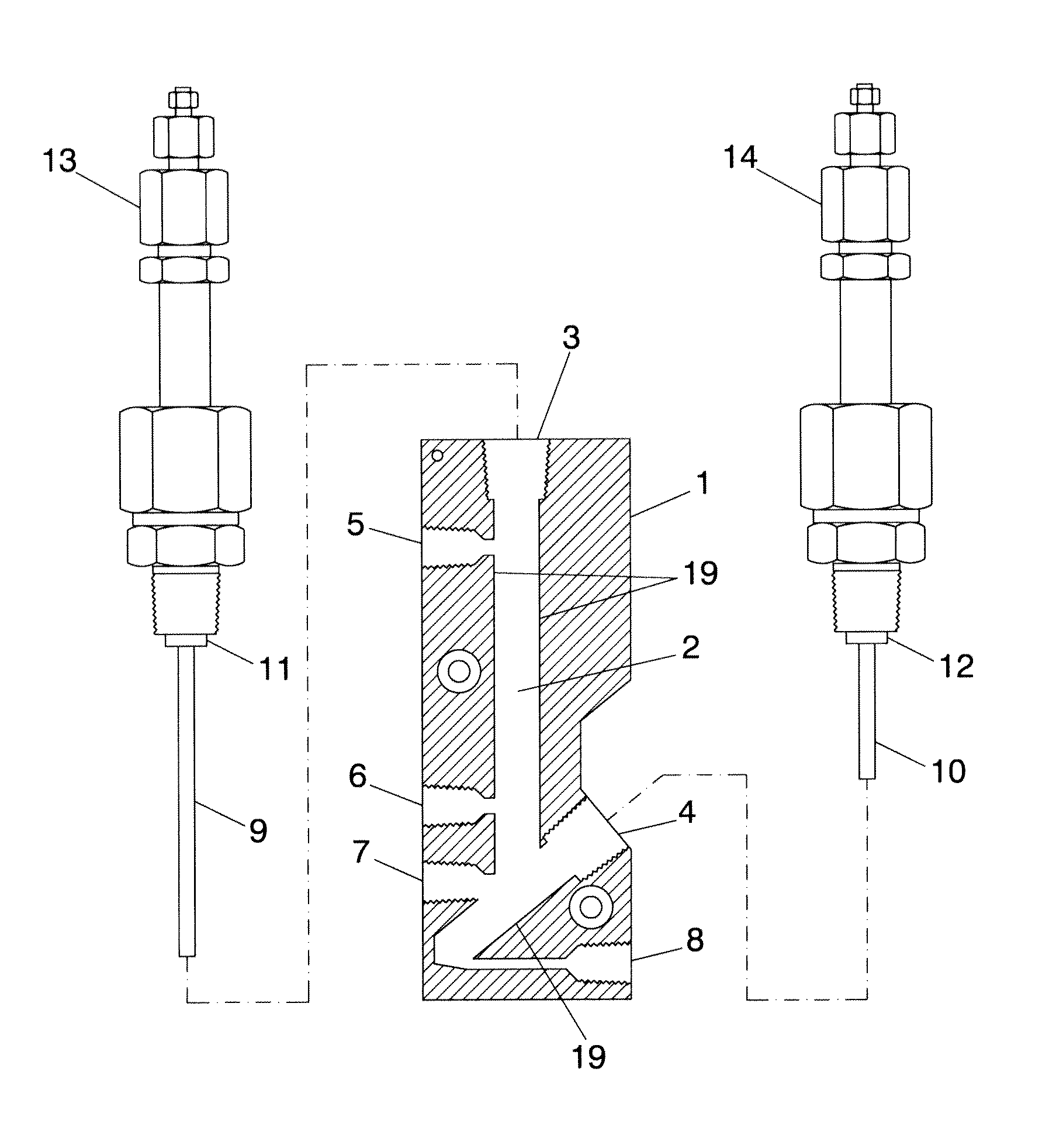
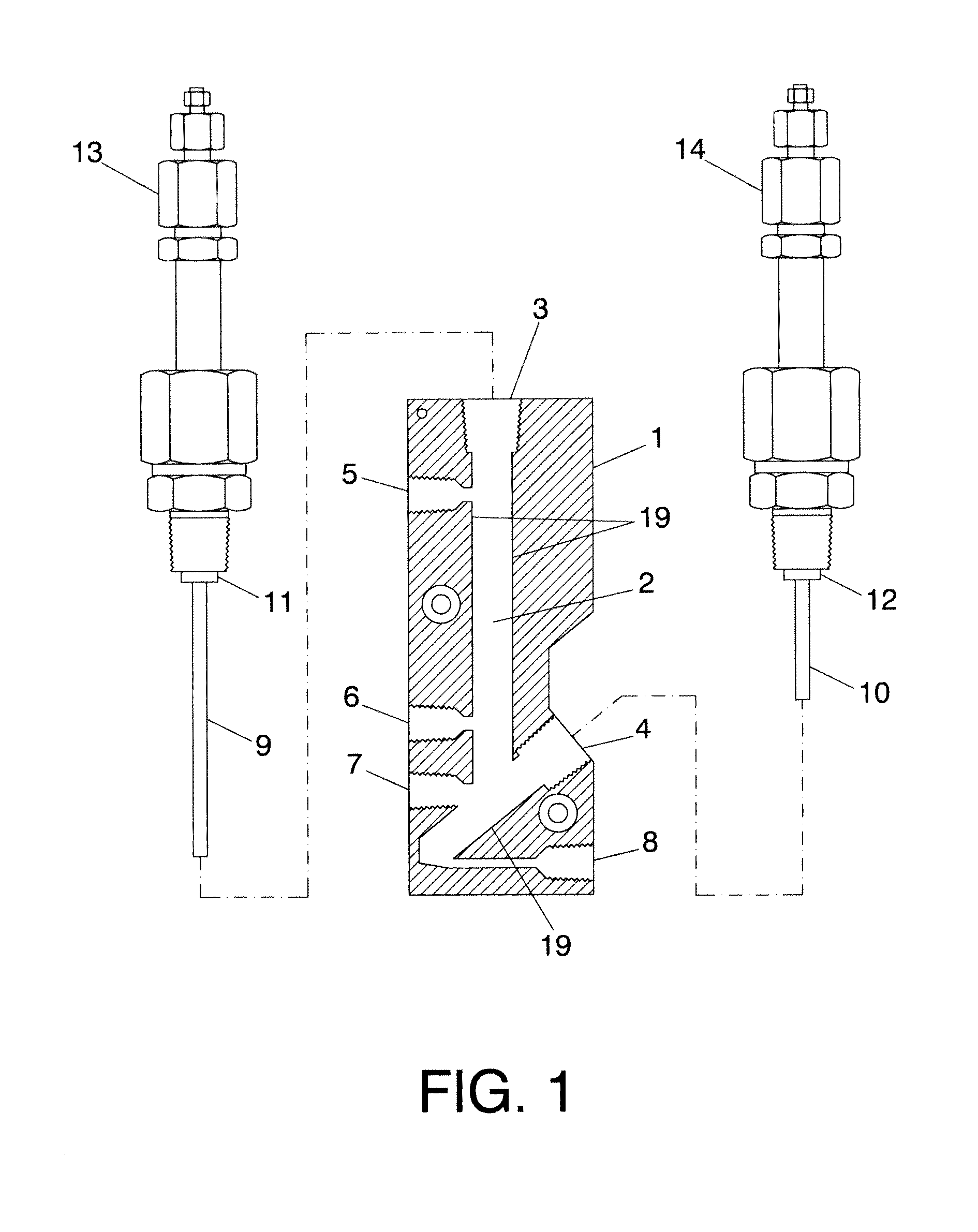
[0022]In light of the figures, below a preferred embodiment of the separator device of this invention is described.

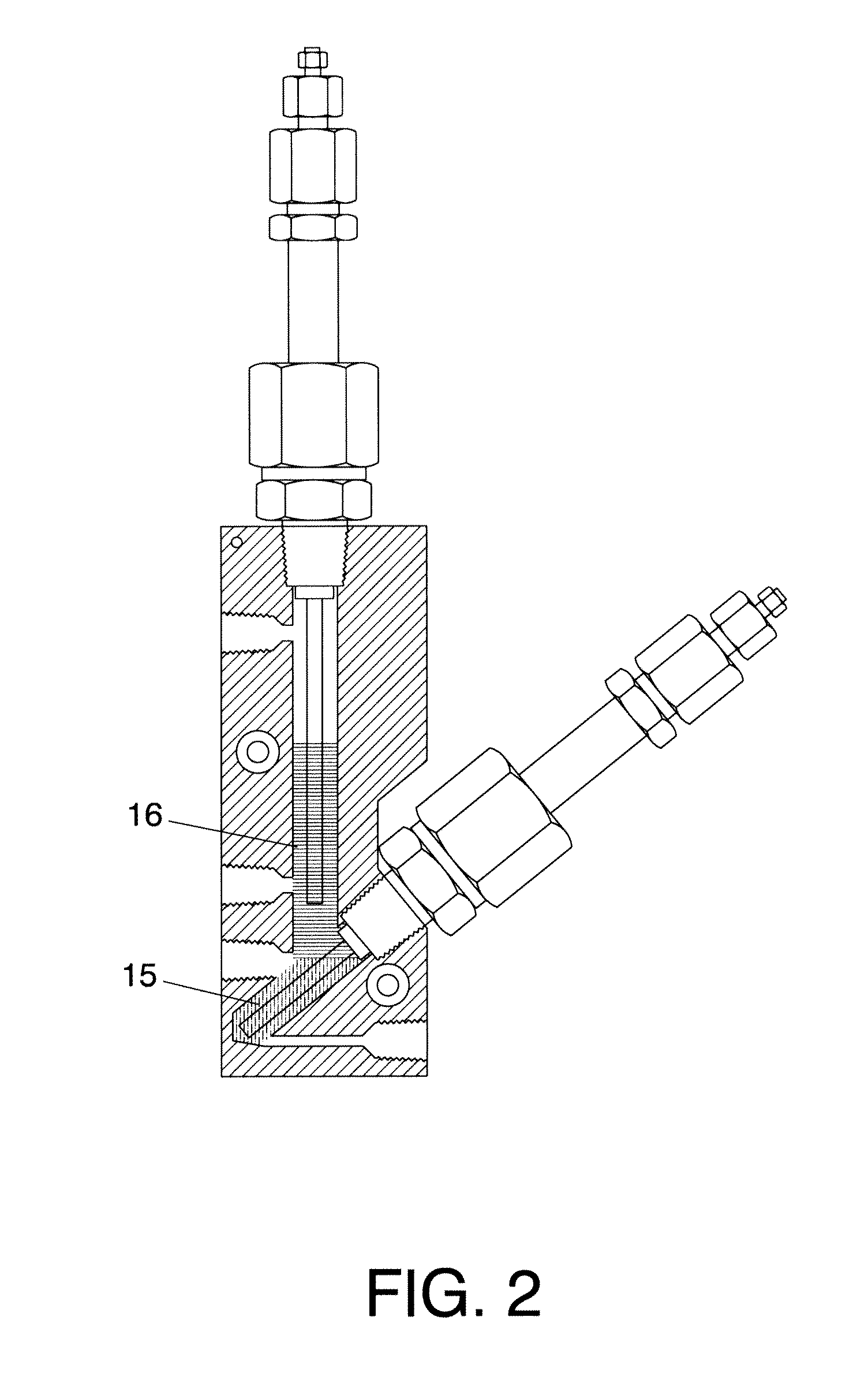
[0023]A number of machinings are performed in a body (1), preferably metallic, in order to generate a tank (2) in the interior thereof which has a complex geometry and a capacity of about 10 cm3, as may be observed in FIG. 1, preferably made of stainless steel, the geometry whereof corresponds to a rectangular parallelepiped with a lateral groove that facilitates the housing of a water probe (10). The tank (2) obtained is endowed with a longitudinally perforated part and an obliquely perforated part. Both have a 9-mm diameter and come together at the level where a fluid inlet (7) is located.

[0024]The tank (2) acts as a thermal condenser to separate three phases, two liquid phases (hydrocarbons and water) and a gaseous phase. Two probes (9) and (10) are placed at both sides of the tank. The tank (2) is perforated in a solid part (1), the geometry whereof corresponds to a...


PUM

PropertyMeasurementUnit
pressuresaaaaaaaaaa
total volume capacityaaaaaaaaaa

Abstract

A device is disclosed which is designed to separate water, hydrocarbons and gases, based on the electric characteristics of the materials; the device utilizes the different capacitance of water and hydrocarbons.

Description

CROSS-REFERENCE TO RELATED APPLICATIONS[0001]The present patent application is a national phase application of International Application No. PCT / ES2010 / 070559, filed Aug. 17, 2010, which application claims priority to Spanish Application No. P 200930603, filed Aug. 17, 2009.FIELD OF THE INVENTION[0002]The present invention relates to a three-phase capacitive separator, of gases, hydrocarbons and water, for very small volume systems.[0003]The object of the invention consists of a device based on a pair of capacitive sensors and has been designed to perform the continuous separation of the gases, hydrocarbons and water obtained as the product of chemical reactions in reactors and micro-pilot- or laboratory-scale processing plants.BACKGROUND OF THE INVENTION[0004]As of today, there are industrial systems capable of separating hydrocarbons and water. The appearance of these two compounds in the fuel tanks of maritime vehicles, during their storage on land, their transport in viaducts or...

Claims


Application Information

Patent Timeline
Patent Type & Authority Patents(United States)
IPC IPC(8): F25J3/00B01D5/00G01F23/26
CPCG01F23/268B01D5/0042G01F23/266
Inventor GOBERNA SELMA, CONSUELOPRIETO BARRANCO, JOSEYANEZ VILLAREAL, DAVID
Owner CONSEJO SUPERIOR DE INVESTIGACIONES CIENTIFICAS (CSIC)
Why Eureka
Try Eureka