Apparatus for preparing food

a technology for preparing food and apparatus, which is applied in the field of apparatus for preparing food, can solve the problems of increasing the cost of the apparatus, injuries or discomfort, and air in the food preparation chamber known to heat up the apparatus housing, so as to improve the reliability of the cooling system, reduce the noise level of the apparatus, and improve the reliability of the components

Active Publication Date: 2016-05-31
VERSUNI HLDG BV
View PDF28 Cites 66 Cited by
  • Summary
  • Abstract
  • Description
  • Claims
  • Application Information

AI Technical Summary

Benefits of technology

[0009]According to the present invention, there is provided an apparatus for preparing food comprising a housing, a food preparation chamber in the housing having an inner wall defining a food receiving space with an air entry aperture and an air discharge aperture, a fan for moving a flow of hot air successively through the air entry aperture, the food receiving space and the air discharge aperture, and an air guide passage for returning the flow of air from the air discharge aperture towards the air entry aperture separate from the food receiving space, the housing comprising a cooling air channel and a hot air vent for exhausting the flow of hot air from the food preparation chamber to outside the housing with a constricted section having a reduced cross-sectional area such that a venturi effect is generated in the hot air vent, wherein an outlet to the cooling air channel communicates with the hot air vent at the constricted section such that a region of low pressure is formed at the outlet and a flow of cooling air is drawn along the cooling air channel and into the hot air vent.
[0024]In view of the forgoing, cooling air may be drawn through the cooling air channel and exhausted from the housing without the need for an additional fan or other components to create a flow. Therefore, the reliability of the cooling system is improved over conventional apparatus due to the absence of moving parts or components in the cooling system.
[0025]In addition, the level of noise generated by the apparatus is minimized.
[0026]Furthermore, air flowing through the component chamber may carry heat away from the components disposed therein and so the reliability of the components will be increased.
[0027]The combined air flow exhausted from the exit of the hot air vent will be at a lower temperature than that of the hot air and other fluids expelled from the food preparation chamber only, and so the likelihood of injury or damage being caused by the fluid exhausted through the hot air vent is minimized. In addition, the velocity of the combined air flowing from the housing is minimized.
[0028]An advantage of the vent and fan being positioned in the upper part of the food preparation chamber is that liquid discharged from the food items is prevented from collecting on the fan and being discharged through the vent.

Problems solved by technology

However, a disadvantage of a conventional apparatus for preparing food is that the hot air in the food preparation chamber is known to heat up the housing of the apparatus.
This may cause injuries or discomfort when a user comes into contact with the housing.
Furthermore, it is also necessary to cool internal components, such as a motor to drive the fan, to prevent the components from overheating and having reliability problems.
However, a problem with the provision of a cooling air fan and channel is that additional components are needed which increases the cost of the apparatus and reduces its reliability.
Furthermore, the fan increases the noise of the apparatus during use.

Method used


Image

  • Apparatus for preparing food
  • Apparatus for preparing food
  • Apparatus for preparing food

Examples


Embodiment Construction

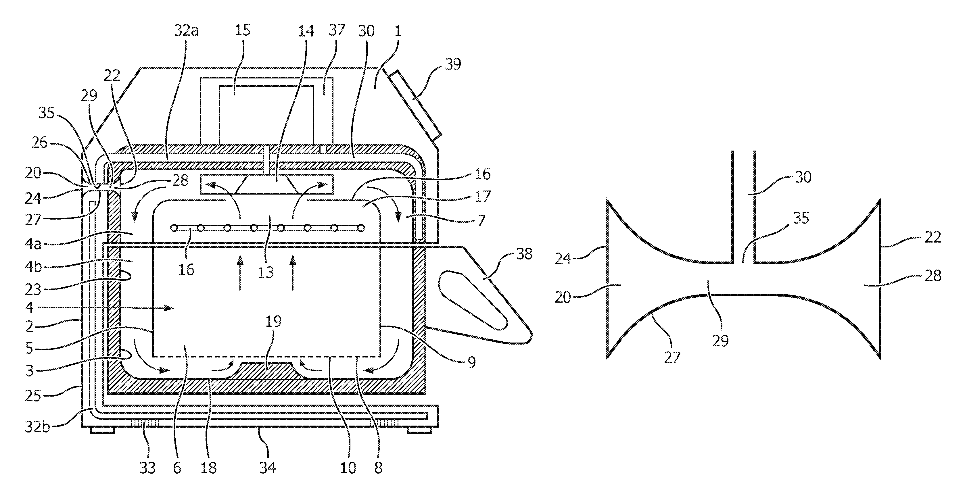
[0034]An apparatus for preparing food is shown in FIG. 1 comprising a housing 1 and a food preparation chamber 4 formed in the housing 1. The apparatus is configured to prepare food items placed therein by heating, so as to heat and / or cook the food items ready for consumption.

[0035]The housing 1 has an outer surface 2 and an inner surface 3 which defines a wall of the food preparation chamber 4. An inner wall 5 is disposed in the food preparation chamber 4 and defines a food receiving space 6 in which food items to be heated and / or cooked (not shown) are received. The inner surface 3 of the housing 1 and the inner wall 5 extend substantially parallel to but spaced from each other to define an air guide passage 7 there between along which hot air is circulated in the food preparation chamber 4, as will be explained hereinafter.

[0036]The inner wall 5 comprises a bottom part 8 and a side wall 9 which extends around and upstands from the bottom part 8. The bottom part 8 of the inner wa...


PUM


Abstract

The application relates to an apparatus for preparing food. The apparatus includes a housing (1), a food preparation chamber (4) in the housing (1) having an inner wall (5) defining a food receiving space (6) with an air entry aperture (10) and an air discharge aperture (13), a fan (14) for moving a flow of hot air successively through the air entry aperture (10), the food receiving space (6) and the air discharge aperture (13), and an air guide passage (7) for returning the flow of air from the air discharge aperture (13) towards the air entry aperture (10) separate from the food receiving space (6). The housing (1) comprising a cooling air channel (30) and a hot air vent (20) for exhausting the flow of hot air from the food preparation chamber (4) to outside the housing (1) with a constricted section (29) having a reduced cross-sectional area such that a venturi effect is generated in the hot air vent (20). An outlet (35) to the cooling air channel (30) communicates with the hot air vent (20) at the constricted section (29) such that a region of low pressure is formed at the outlet (35) and a flow of cooling air is drawn along the cooling air channel (30) and into the hot air vent (20).

Description

CROSS-REFERENCE TO PRIOR APPLICATIONS[0001]This application is the U.S. National Phase application under 35 U.S.C. §371 of International Application No. PCT / IB2012 / 052881, filed on Jun. 7, 2012, which claims the benefit of European Patent Application No. 11168899.0, filed on Jun. 7, 2011. These applications are hereby incorporated by reference herein.FIELD OF THE INVENTION[0002]The present invention relates to an apparatus for preparing food. In particular, the present invention relates to an apparatus for preparing food by moving a flow of hot air over items of food to heat them.BACKGROUND OF THE INVENTION[0003]An apparatus for preparing food is known from EP 2 034 872 B1. The apparatus is generally used in a domestic setting and provides a means of preparing food for eating by circulating a flow of hot air around the food items to heat and / or cook the food. Such an apparatus generally comprises a housing with an enclosed food preparation chamber, into which food items are placed a...

Claims


Application Information

Patent Timeline
Patent Type & Authority Patents(United States)
IPC IPC(8): F24C15/32F24C7/04A47J37/06A47J39/00A21B3/04F24C15/20A21B1/26
CPCF24C7/043A21B3/04A47J37/0641A47J39/003F24C7/04F24C15/2007F24C15/325A21B1/26
Inventor LINNEWIEL, REMCO
Owner VERSUNI HLDG BV
Why Eureka
Try Eureka