Temperature control module for a socket

a temperature control module and socket technology, applied in the direction of electrical apparatus casings/cabinets/drawers, instruments, semiconductor/solid-state device details, etc., can solve the problem of difficult to precisely and uniformly control the temperature of the test environmen

Active Publication Date: 2016-05-31
CHROMA ATE
View PDF14 Cites 2 Cited by
  • Summary
  • Abstract
  • Description
  • Claims
  • Application Information

AI Technical Summary

Benefits of technology

[0009]A main objective of the present invention is to provide a temperature control module for a socket, which can continuously maintain the socket at a high-temperature or low-temperature state in order to put a chip to be tested completely under a predetermined high-temperature or low-temperature environment. As such, a test result can be obtained more precisely. It is more important that a test can be progressed quickly, since it is unnecessary to take any waiting time to heat or cool the chip to be test.
[0011]Accordingly, by accommodating the socket in the fluid chamber filled with the temperature controlling fluid, the socket can be heated or cooled all the time so as to maintain at a specific temperature. As in cooperation with a chip pressing mechanism having a temperature control function, located above the socket, a chip to be test is surrounded in a test environment at predetermined temperature. Therefore, on one hand the accuracy of chip test can be enhanced, and on the other hand test efficiency can be significantly promoted.
[0012]The fluid chamber of the invention can be formed by the recess of the upper docking plate, the upper surface of the lower docking plate and the surrounding sidewalls of the socket. As such, the surrounding sidewalls of the socket is in contact with the temperature controlling fluid directly to perform heat exchange for increasing or decreasing temperature. Additionally, the present invention can further comprise a gasket for sealing the upper docking plate and the lower docking plate therebetween. The gasket is opened with a through hole corresponding to the recess of the upper docking plate. Accordingly, by bring the upper docking plate and the lower docking plate to a sealing state with the gasket, the present invention can prevent the temperature controlling fluid from leaking. The gasket can be formed of high-density foam, rubber, silica gel or other equivalent sealing material with elasticity property.
[0013]Furthermore, the upper docking plate can comprise two temperature controlling fluid passages. An opening is provided on each of the two end sides of a sidewall of the recess of the upper docking plate. The two temperature controlling fluid passages communicates with the openings, respectively. Accordingly, the two temperature controlling fluid passages are for the input and output passages of the temperature controlling fluid, respectively. Moreover, the input and output openings are disposed on the two end sides of the sidewall of the recess, such that the temperature fluid can flow along the surrounding sidewalls of the socket and perform heat exchange. As a result, a better temperature control effect can be obtained.
[0014]Preferably, the lower docking plate of the present invention can be a circuit load board electrically which is matched with the socket. In other words, the circuit load board for the socket can serve as the lower docking plate, directly, and the socket is electrically connected with the circuit load board for transmitting electrical signal. Furthermore, for removing the problem that water vapor inclines to condense under a low-temperature test environment, the present invention can further comprises a dry air kit, disposed bellow the lower docking plate. The dry air kit has an outlet directed toward the lower docking plate. Accordingly, dry air can be directed toward the lower docking plate, in order to prevent the lower docking plate from being moistened and causing circuits to be out of work.

Problems solved by technology

Nevertheless, this temperature control means can only heat or cool the top portion of the electronic device to be tested, such that it is difficult to precisely and uniformly control the temperature of the test environment.

Method used


Image

  • Temperature control module for a socket
  • Temperature control module for a socket
  • Temperature control module for a socket

Examples


Embodiment Construction

[0020]Before describing a temperature control module for a socket of the present invention in this embodiment, it should be noted that the similar elements are designated with the same reference numeral in the following description.

[0021]A temperature control module for a socket provided in this embodiment is used to cooperate with a chip pressing mechanism (not shown in the figures of the drawings). However, it is not limited to this, and can also be used in cooperation with other components or alone, depending on actual requirements.

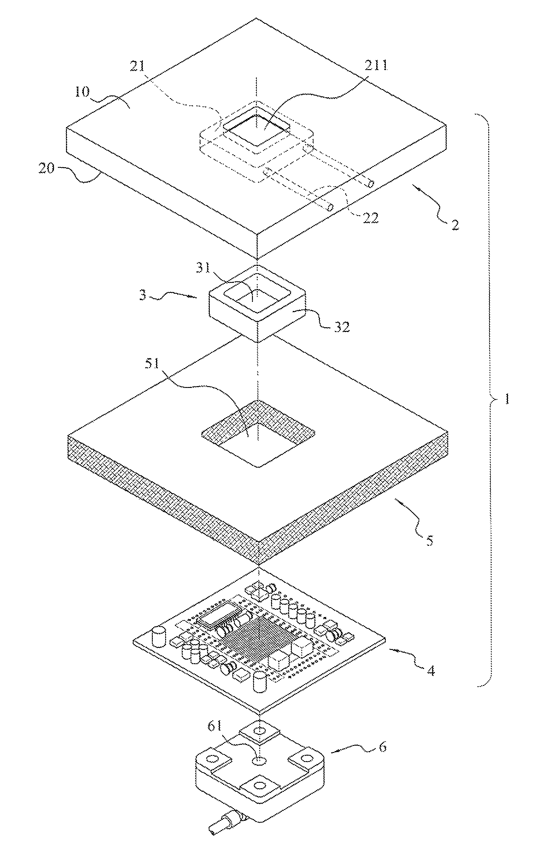
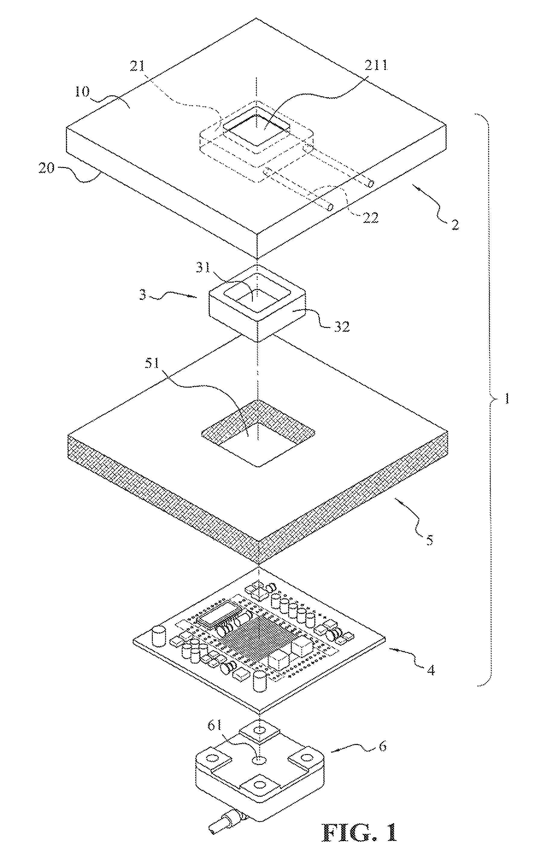
[0022]Referring to FIG. 1 and FIG. 2 at the same time, FIG. 1 is an exploded view of a preferred embodiment of a temperature control module for a socket of the present invention, and FIG. 2 is a cross-sectional view of the preferred embodiment of the temperature control module for the socket of the present invention. The embodiment mainly comprises an upper docking plate 2, a socket 3, a lower docking plate 4, a gasket 5, and a dry air kit 6. However, ...


PUM


Abstract

A temperature control module for a socket is provided with of an upper docking plate and a lower docking plate. The upper docking plate has a recess for accommodating a socket and two temperature-controlling fluid passages. One end of the passages communicates with the recess, and the other end thereof is connected to a temperature-controlling fluid source. The lower docking plate is disposed under the upper docking plate and covers the recess. A fluid chamber is formed of the recess of the docking plate, the lower docking plate and the socket. The temperature-controlling fluid source outputs a temperature-controlling fluid to the fluid chamber via the temperature-controlling fluid passages for maintaining the socket at a specific temperature.

Description

BACKGROUND OF THE INVENTION[0001]1. Field of the Invention[0002]The invention relates to a temperature control module for a socket, and particularly to a temperature control module suitable for providing test environment with different temperatures for testing electronic components.[0003]2. Description of the Related Art[0004]Generally speaking, after electronic components have been accomplished through a series of manufacturing processes, for most of electronic components, they have to be tested with a test instrument to ensure they can be normally operated. However, for testing of electronic components, it is a very important task to test the electronic components under high-temperature or low-temperature environment.[0005]Under the current technical circumstances, most of high-temperature or low-temperature tests are prepared by using a temperature control device. Hence, when the temperature control device directly contacts an electronic component to be tested, it will be heated ...

Claims


Application Information

Patent Timeline
Patent Type & Authority Patents(United States)
IPC IPC(8): G06F1/16H05K7/00H05K5/00F28D15/00H01L23/473
CPCF28D15/00H01L23/473H01L2924/0002H01L2924/00
Inventor WU, XIN-YICHOU, JUI-CHIHSHEN, HSUAN-JEN
Owner CHROMA ATE
Why Eureka
Try Eureka