Clot removal device and method of using same

a technology of clot removal and a device, applied in the field of medical devices, can solve the problems of reducing the oxygen amount of the blood supply, affecting the function of the brain,

Active Publication Date: 2016-06-07
MORSI HESHAM
View PDF79 Cites 21 Cited by
  • Summary
  • Abstract
  • Description
  • Claims
  • Application Information

AI Technical Summary

Benefits of technology

[0008]In one embodiment, the device further comprises a radiopaque marker. In another embodiment, the frame component is configured to fit within a catheter for delivery to the obstruction and to expand to define the open end when released from the catheter, the catheter having a radius smaller than a radius of the open end. In one embodiment, the frame component comprises a self-expanding material configured to have an original configuration and a deformed configuration; where the self-expanding material is configured to change from the deformed configuration to the original configuration at least by exposure to an activating condition. In another embodiment, the deformed configuration allows the device to fit within the catheter.

Problems solved by technology

Because arterial blockages reduce blood flow through the affected vessel, any blockage or obstruction can lead to many serious medical complications as tissue relying on the blood's supply of oxygen may become damaged due to the decrease in the oxygen amount.
For instance in the brain circulation this can lead to stroke with loss of vital brain functions and / or death, while in the heart it can lead heart attack due to damage of the heart muscle with significant impairment of its ability to pump blood to the body organ which can eventually lead to death.
While various methods and devices are available to treat a blockage or obstruction through removal of the obstructing clot, these devices can be traumatic to the blood vessel due to stiffness and pressure exerted on the lining of the vessel during clot engagement and removal.
In addition, they usually do not sufficiently capture and retain the particulate matters from the obstruction.
In particular, these methods usually cause fragmentation of the clot either during device engagement of the clot or due to the friction between the not fully encapsulated clot with the wall of the vessels or the flowing blood during the removal from the body.
This fragmentation of the clot can lead to migrating of clot fragments with the blood flow either to the same treated blood vessels and its branches distal to the original obstruction site or to another unaffected area of the vascular system in the branching circulation at or proximal to the site of the obstruction where they can get lodged again and causes further obstruction.

Method used


Image

  • Clot removal device and method of using same
  • Clot removal device and method of using same
  • Clot removal device and method of using same

Examples


Embodiment Construction

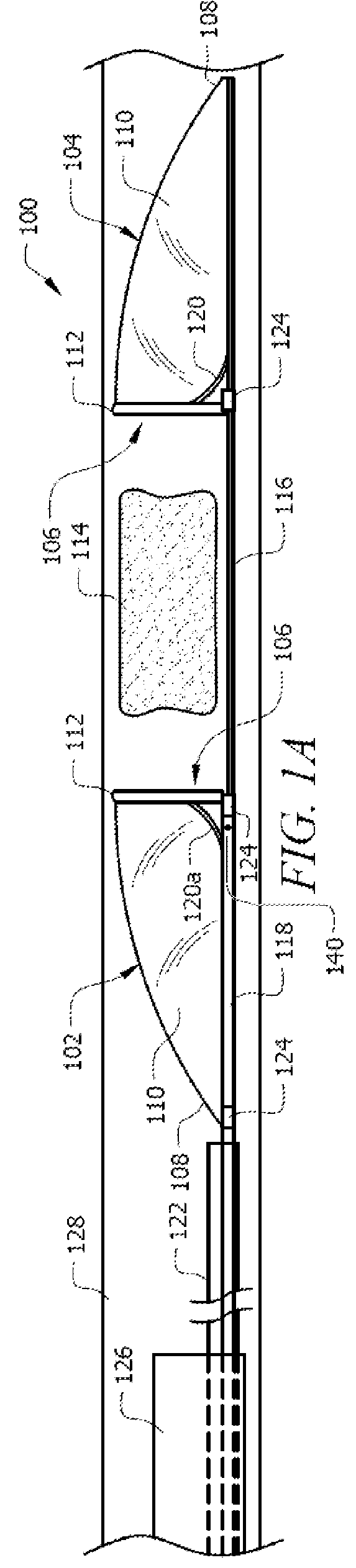
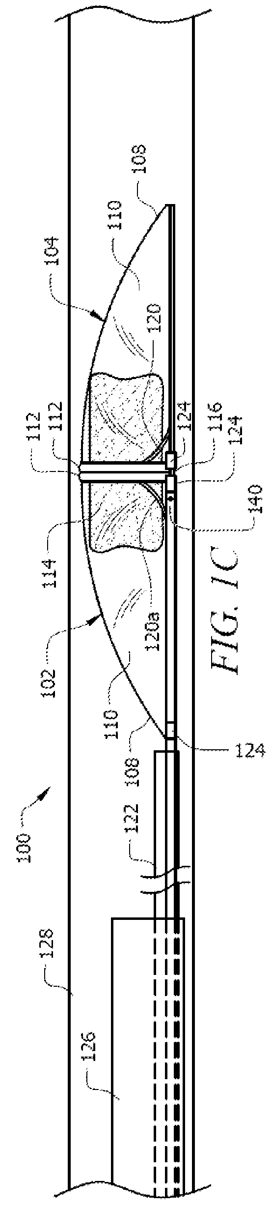
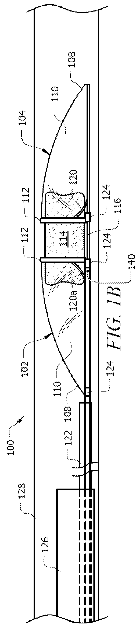
[0027]Embodiments of the present invention provide for minimally invasive removal of obstructing material, such as a clot or embolism, disposed in a patient's (human or otherwise) vascular system. Certain embodiments of the present invention are particularly applicable for extraction of material in small, tortuous and highly branching segments of the neurovascular system. In a general embodiment, the endovascular device of the present invention includes two opposing capture members that are slidably coupled to each other. Each capture member preferably comprises an open end and a tapered end, where the open end of each capture member faces one another. In one embodiment, the endovascular device can be delivered to the site of the material deposit using a catheter. The capture members can be placed on each side of the material deposit with the open ends facing the material deposit. In one embodiment, the open end of each capture member is supported by a frame component. In another em...


PUM


Abstract

A minimally invasive endovascular device for treating a blocked or obstructed biological lumen, such as a blood vessel fully or partially obstructed by deposits of biological matters in or non-biological matters. Certain embodiments of the present invention comprise two capture members that are configured to be placed on either side of the obstruction and enclose around the obstruction for removal. Embodiments of the present invention also provide methods for implementing an endovascular device according to aspects of the present invention.

Description

CROSS-REFERENCE TO RELATED APPLICATIONS[0001]This application claims priority to U.S. Provisional Application No. 61 / 688,784, filed on May 21, 2012, the disclosure of which is incorporated by reference.TECHNICAL FIELD[0002]Embodiments of the present invention relate generally to medical devices and methods of using same, and more specifically, to medical devices for treating or treating an occluded biological lumen, such as an embolus or clot in a blood vessel.BACKGROUND OF THE INVENTION[0003]This section is intended to introduce various aspects of the art, which may be associated with exemplary embodiments of the present invention. This discussion is believed to assist in providing a framework to facilitate a better understanding of particular aspects of the present invention. Accordingly, it should be understood that this section should be read in this light, and not necessarily as any admission of prior art.[0004]There are many reasons a blood vessel becomes blocked or obstructed...

Claims


Application Information

Patent Timeline
Patent Type & Authority Patents(United States)
IPC IPC(8): A61B17/221A61F2/01A61B17/00
CPCA61B17/221A61F2/013A61F2230/0067A61B2017/00287A61B2017/2212A61F2002/018A61B2017/00867A61B2017/22035A61B2017/22038A61B2017/22051A61B2017/22094A61B2017/2215A61B2090/3966A61B17/22032A61B2017/22072A61B2017/22079
Inventor MORSI, HESHAM
Owner MORSI HESHAM
Why Eureka
Try Eureka