High torque, low profile catheters and methods for transluminal interventions

a catheter and low-profile technology, applied in the field of catheters, to achieve the effect of increasing the likelihood of lateral deploymen

Active Publication Date: 2014-01-28
MEDTRONIC VASCULAR INC
View PDF19 Cites 9 Cited by
  • Summary
  • Abstract
  • Description
  • Claims
  • Application Information

AI Technical Summary

Benefits of technology

[0014]In accordance with the present invention there is provided a catheter device comprising i) an elongate catheter body, at least a portion of which comprises a) a core member having at least one lumen extending therethrough, b) a substantially cylindrical braided layer disposed about the core member and c) an outer layer disposed about said braided layer and ii) a laterally deployable member that is advanceable or extendable laterally from the catheter body. At least the core member of the catheter body is formed of material that is sufficiently lubricious to allow a guidewire or other member to advance through the lumen of the core member without the need for placement of a lubricious liner within the lumen. Also, in at least some embodiments, the construction of the catheter body is such that it has a diameter of no more than 0.080 inch and in some cases in the range of from about 0.067 inch to abut 0.080 inch. In some embodiments, the diameter of the catheter body is small enough to allow it to pass through a standard 6 French introducer sheath. In some embodiments, the laterally deployable member may comprises a tubular member (e.g., a cannula or hollow needle) and may be formed of elastic or superelastic material and biased to a curved configuration. Also, in some embodiments, one or more imageable marker(s) or other imageable elements of the catheter device may be imaged by radiographic or other imaging means and may be configured to indicate the direction or trajectory on which the laterally deployable member will extend or advance from the catheter body. An image of such marker or other element may thus be used by the operator to adjust the position and / or rotational orientation of the catheter body in situ to increase the likelihood that the laterally deployable member will subsequently extend or advance into a desired target location (e.g., within the true lumen of a blood vessel) rather than to some other unintended location.

Problems solved by technology

In many CTO cases, a guidewie can be advanced around the obstructive lesion, but this typically results in the distal portion of the guidewire penetrating or dissecting into the artery wall such that a distal portion of the guidewire becomes entrapped in a subintimal space (e.g., a dead-end channel created by advancement of the guidwire within the artery wall next to the obstruction).

Method used


Image

  • High torque, low profile catheters and methods for transluminal interventions
  • High torque, low profile catheters and methods for transluminal interventions
  • High torque, low profile catheters and methods for transluminal interventions

Examples


Embodiment Construction

[0024]The following detailed description, the accompanying drawings are intended to describe some, but not necessarily all, examples or embodiments of the invention. The contents of this detailed description and accompanying drawings do not limit the scope of the invention in any way.

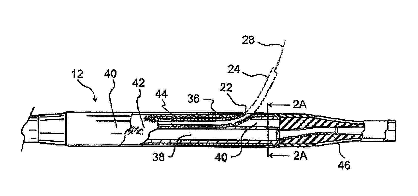
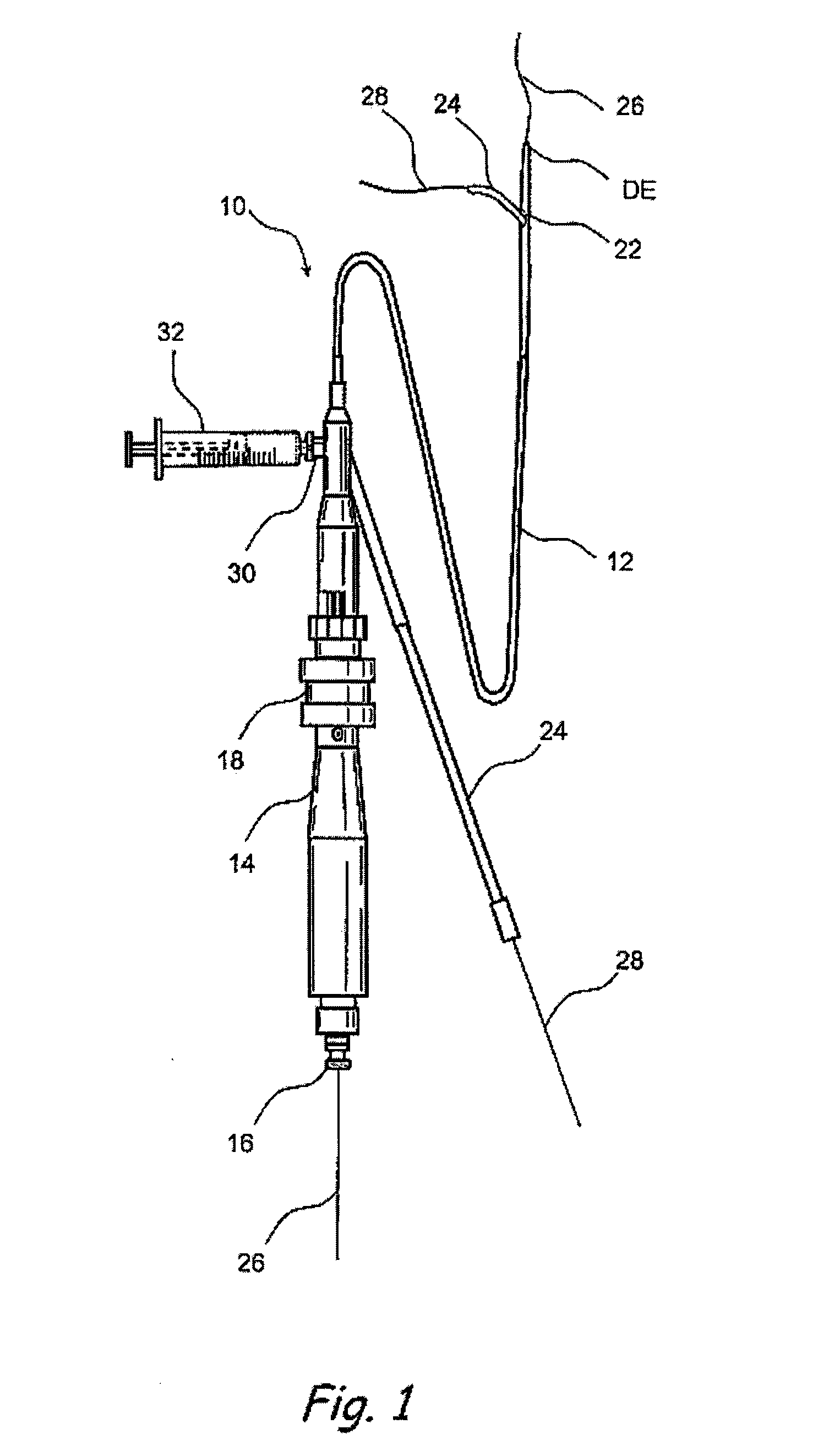
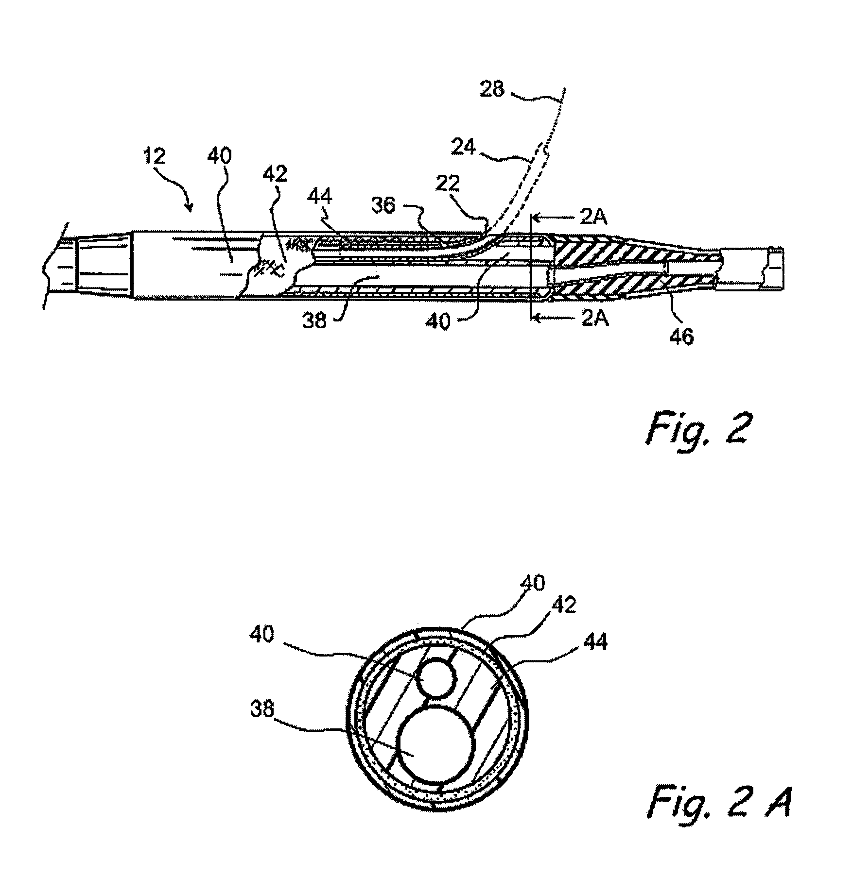
[0025]FIGS. 1-2B show one example of a catheter device 10 of the present invention. This catheter device 10 comprises an elongate catheter body 12 (e.g., a catheter shaft) having an atraumatic distal tip member 46 on its distal end DE and a handpiece 14 on its proximal end. As shown specifically in FIG. 2B, the catheter body 12 comprises a core member 44, a braid layer 42 surrounding the core member 44 and an outer layer 40 surrounding the braid layer 42. These components 40, 42, 44 of the catheter body 12 may be formed of materials that provide the desired strength and torque transmission while minimizing the overall diameter of the catheter body 12. For example, the core member 44 may comprise machine...


PUM

PropertyMeasurementUnit
outer diameteraaaaaaaaaa
tip angleaaaaaaaaaa
tip angleaaaaaaaaaa

Abstract

Catheter devices having low profile shafts and laterally deployable members (e.g., cannulas, needles, etc.) that may be extended or advanced laterally from the catheter shaft. Also disclosed are methods for bypassing a vascular obstruction (e.g., a chronic total occlusion or other full or partial obstruction) wherein a guidewire is entrapped in a subintimal space adjacent to the obstruction. A catheter of the foregoing character is advanced over the entrapped guidewire and into the subintimal space. The laterally deployable member is then advanced or extended from the subintimal space back into the true lumen of the blood vessel distal to the obstruction. A second guidewire is then advanced through or along the laterally deployable member. The catheter and first guidewire are then removed and one or more working device(s) (balloons, atherectomy devices, setnts, etc.) is / are advanced over the second guidewire and used to establish a subintimal bypass channel through which blood may flow around the obstruction.

Description

FIELD OF THE INVENTION[0001]The present invention relates generally to methods and apparatus for medical treatment and more particularly to catheters and related methods for vascular and other transluminal interventional procedures.BACKGROUNDCatheters Having Laterally Deployable Members[0002]The prior art has included a variety of intravascular catheters that have laterally deployable members (e.g., wires, needles, other catheters, probes, etc.) which advance or extend laterally from the body of the catheter. In some applications, these catheters are used to direct a laterally deployable member into a furcation, side branch or other angulation vessel. In other applications, the laterally deployable members are caused to penetrate through tissue or other matter within the body to reach some desired target location.[0003]U.S. Pat. No. 4,774,949 (Fogarty) describes a deflector guiding catheter having a lumen that extends through the catheter and terminates distally in a side outlet ope...

Claims


Application Information

Patent Timeline
Patent Type & Authority Patents(United States)
IPC IPC(8): A61M25/00
CPCA61M25/005A61M25/007A61M25/0606A61M25/003A61M25/0045A61M25/0108A61M25/0084A61M2025/0037A61M2025/0092A61M2025/0197
Inventor PATEL, KAUSHIK
Owner MEDTRONIC VASCULAR INC
Why Eureka
Try Eureka