Flywheel-powered vehicle

a technology of flywheels and vehicles, applied in mechanical equipment, rotary machine parts, transportation and packaging, etc., can solve the problems of unavailability of gasoline and the inability to fully exploit the full extent of flywheels

Active Publication Date: 2016-06-07
SHERRY RAYMOND C
View PDF9 Cites 14 Cited by
  • Summary
  • Abstract
  • Description
  • Claims
  • Application Information

AI Technical Summary

Benefits of technology

[0011]According to an embodiment of the invention, disclosed is a vehicle driven by a rotary power source, where the vehicle includes a flywheel adapted for rotation. The flywheel rotates about a vertical axis so that left and right turns o

Problems solved by technology

Even gasoline was not readily available at that time to make the internal combustion engine widely used.
While flywh

Method used


Image

  • Flywheel-powered vehicle
  • Flywheel-powered vehicle
  • Flywheel-powered vehicle

Examples


Embodiment Construction

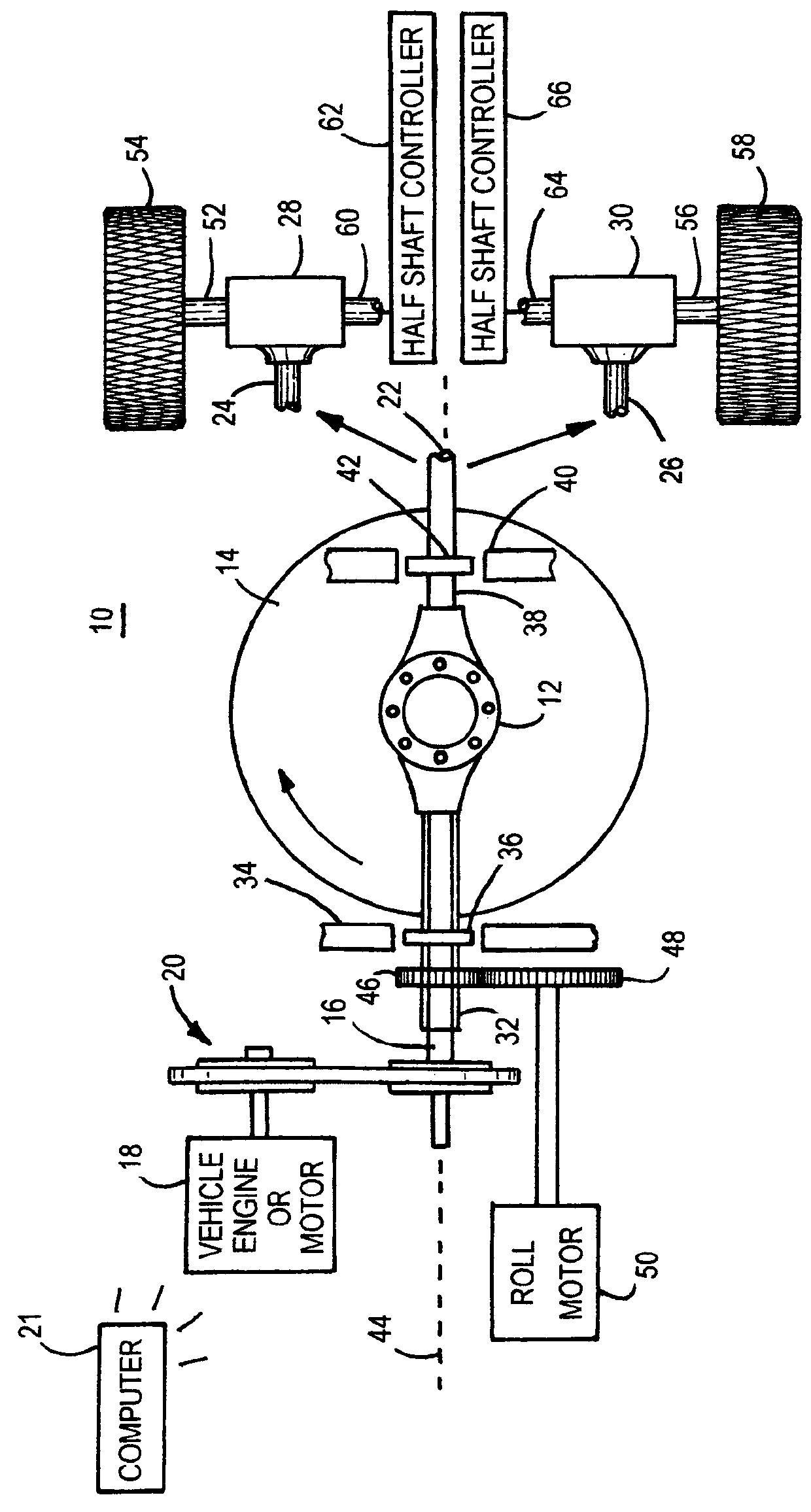
[0022]With reference to FIG. 1, there is illustrated an embodiment of the drive train 10 of a flywheel-equipped vehicle. The drive train 10 includes a main differential 12 of conventional construction. The main differential gear mechanism 12 includes a standard ring, pinion and spider gear. The main differential 12 includes a vertical drive shaft (not shown) connected to a flywheel 14. One half shaft 16 of the main differential 12 is connected to an engine 18 via a chain or belt and pulley system 20. The pulley system 20 can include a magnetic clutch that can be engaged to disconnect the engine from the drive train when, for example, slowing the vehicle down so that the engine is not attempted to be driven by the vehicle. Rather, when the vehicle is slowing down, the kinetic energy is captured and stored in the flywheel 14. Alternatively, the half shaft 16 can be driven directly by the engine 18 via a standard or automatic transmission. In hybrid type vehicles, the half shaft 16 can...


PUM


Abstract

A flywheel operated vehicle. The engine drives the flywheel using a differential axle, while also driving a pair of other differentials each of which is connected to a respective drive wheel. The rotation of half shafts of the pair of differentials are controlled to determine the extent of power transferred from the flywheel to the drive wheels during acceleration, and determines the power transferred from the drive wheels to the flywheel during deceleration of the vehicle. The flywheel can be tilted about a roll axis of the vehicle to counteract roll tendencies of the vehicle when turning a sharp corner.

Description

RELATED APPLICATION[0001]This non-provisional patent application claims the benefit of U.S. provisional patent application filed Jul. 31, 2013 and assigned Ser. No. 61 / 958,560.TECHNICAL FIELD OF THE INVENTION[0002]The present invention relates in general to power sources for vehicles, and more particularly to flywheels for powering vehicles.BACKGROUND OF THE INVENTION[0003]The internal combustion engine has been a great innovation to provide rotary power for driving many different types of machines. Gasoline powered engines of this type were developed in the 1860's to power early machines. Even gasoline was not readily available at that time to make the internal combustion engine widely used. The internal combustion is today the mainstay for powering automobiles and other vehicles. Most engines employ an internal flywheel to smooth out the power delivery from the engine to the load. In other words, the typical engine flywheel stores kinetic energy during engine ignition cycles, and ...

Claims


Application Information

Patent Timeline
IPC IPC(8): B60G17/06F16F15/00F16F15/30B60K6/10F16C15/00B60W30/04
CPCB60K6/105F16C15/00F16F15/30B60G17/06B60W30/04B60G2800/9122Y02T10/62
Inventor SHERRY, RAYMOND C.
Owner SHERRY RAYMOND C
Why Eureka
Try Eureka