Cowl-top cover

a technology of top cover and cowl, which is applied in the direction of pedestrian/occupant safety arrangement, vehicle components, superstructure subunits, etc., can solve the problems of excessive resistance force, achieve the effect of reducing thickness, reducing resistance force with respect to load, and improving related appearan

Active Publication Date: 2016-06-07
NIHON PLAST CO LTD
View PDF11 Cites 2 Cited by
  • Summary
  • Abstract
  • Description
  • Claims
  • Application Information

AI Technical Summary

Benefits of technology

[0013]A cowl-top cover according to a fourth aspect of the present invention is directed to the cowl-top cover according to the first aspect, and is provided in such a manner that the low rigidity portion comprises a small thickness portion formed in a longitudinal direction intermittently while the back face of the cover main body portion is reduced in thickness.
[0014]In so far as the cowl-top cover according to the first aspect of the present invention is concerned, an engagement portion is inserted, in a direction crossing a wind shield face, into an engagement receptacle portion disposed at an edge part of the wind shield. For example, the edge part of the wind shield and a cover main body portion can be caused to be continuous so as to be in flush with each other; its related appearance is improved; and in a case where a load is applied in the direction crossing the wind shield face, a stress concentrates on a low rigidity portion, the cover main body portion is deformed while the low rigidity portion is defined as a start point, and a resistance force with respect to the load can be restrained.
[0015]In so far as the cowl-top cover according to the second aspect of the present invention is concerned, in addition to the advantageous effect of the cowl-top cover according to the first aspect of the present invention, a low rigidity portion is formed at a part of a bending portion continuous to a flat plate portion disposed substantially in parallel to a wind shield face, the bending portion being folded and bent in a direction crossing the wind shield face, whereby, when a load is applied in the direction crossing the wind shield face, a stress is more likely to concentrate on the low rigidity portion, a cover main body portion is deformed more reliably while the low rigidity portion is defined as a start point, and a resistance force with respect to the load can be restrained more reliably.
[0016]In so far as the cowl-top cover according to the third aspect of the present invention is concerned, in addition to the advantageous effect of the cowl-top cover according to the second aspect of the present invention, a back face of at least a part of a portion other than a low rigidity portion of a bending portion is reduced in thickness; and therefore, when a load is applied in a direction crossing a wind shield face, a cover main body portion is deformed more reliably from the low rigidity portion and the bending portion, and a resistance force with respect to the load can be restrained more reliably.
[0017]In so far as the cowl-top cover according to the fourth aspect of the present invention is concerned, in addition to the advantageous effect of the cowl-top cover according to the first aspect of the present invention, a low rigidity portion comprises a small thickness portion formed in a longitudinal direction intermittently while a back face of a cover main body portion is reduced in thickness; and therefore, when a load is applied in a direction crossing a wind shield face, a cover main body portion is deformed more reliably while the low rigidity portion is defined as a start point, a resistance force with respect to this load can be restrained more reliably, and the low rigidity portion cannot be seen from the outside of a motor vehicle in a state in which the cowl-top cover is mounted, and further, its related appearance is improved more remarkably.

Problems solved by technology

However, in the case of this construction, when a load is applied from an upper side to a lower side of the bonnet / hood, for example, a direction of engagement between the engagement receptacle portion and the cover mounting portion and a loading direction are the same as each other; and therefore, the engagement receptacle portion and the cover mounting portion are not disengaged from each other, and there is a danger that an excessive resistance force takes place owing to bottoming of the cowl-top cover that has been deformed in compliance with the applying of the load.

Method used


Image

  • Cowl-top cover
  • Cowl-top cover
  • Cowl-top cover

Examples


Embodiment Construction

[0028]Hereinafter, a cowl-top cover according to a first embodiment of the present invention will be described with reference to the accompanying drawings.

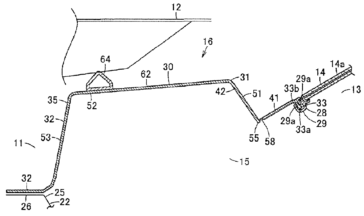
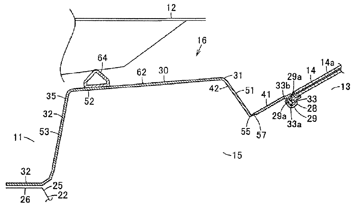
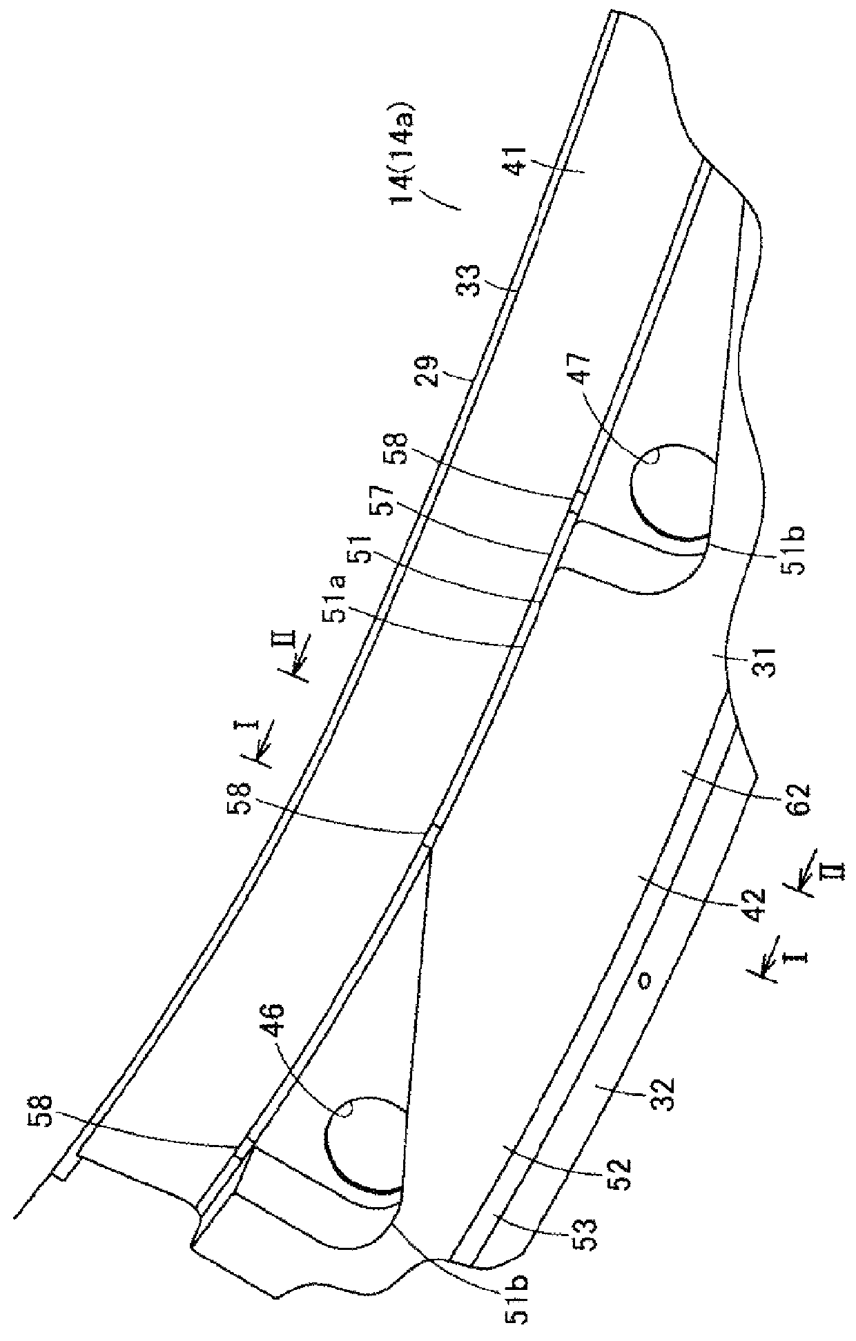
[0029]In FIG. 1 to FIG. 6, reference numeral 10 designates a vehicle body of a motor vehicle, and in the vehicle body 10, a cowl-top cover 16 is mounted to the vehicle body 10 in such a manner as to cover a cowl portion 16 between a hood 12 serving as a counterpart member adapted to cover an engine room 11 and a front glass 14 serving as a wind shield which is positioned on a front side of a vehicle chamber 13. It is to be noted that, hereinafter, directions such as a forward and backward direction, a vertical direction, and a lateral direction will be described with reference to a cruising direction of the vehicle body 10, a direction indicated by the arrow F designates a forward direction, a direction indicated by the arrow U designates an upward direction, and a direction indicated by the arrow W designates a vehicle widthwise ...


PUM


Abstract

A cowl-top cover capable of restraining a resistance force with respect to a load from a direction crossing a front glass face while improving its related appearance is provided. A cover main body portion is provided with a cover mounting portion adapted to be inserted into and engaged with, in a direction crossing a front glass face, an engagement receptacle portion disposed along a longitudinal direction at an edge part of a front glass from one end part in the longitudinal direction. The cover main body portion is provided with a low rigidity portion along the longitudinal direction at a position spaced from the cover mounting portion to an opposite side to the front glass.

Description

CROSS REFERENCE TO RELATED APPLICATIONS[0001]This application claims priority of Japanese Patent Application No. 2014-003538 filed on Jan. 10, 2014. The contents of this application are incorporated herein by reference in their entirety.BACKGROUND OF THE INVENTION[0002]1. Field of the Invention[0003]The present invention relates to a cowl-top cover provided with a cover main body portion disposed at an edge part of a wind shield as a vehicle widthwise direction is defined as a longitudinal direction.[0004]2. Description of the Related Art[0005]Conventionally, there has been employed a cowl-top cover which is disposed at a so called cowl portion between a front end part of a front glass and a rear side part of a bonnet / hood of a motor vehicle, the cowl-top cover being adapted to cover this cowl portion to thereby improve its related appearance. Such a cowl-top cover is provided with a plate-shaped cover main body portion adapted to cover the cowl portion; a cover mounting portion for...

Claims


Application Information

Patent Timeline
Patent Type & Authority Patents(United States)
IPC IPC(8): B62D25/08
CPCB62D25/081B60R21/34
Inventor HAYAKAWA, NORIOOSADA, HIDEHIKOTAKEI, DAISUKEONUMA, NAOTO
Owner NIHON PLAST CO LTD
Why Eureka
Try Eureka