Avionics cargo hold module having an upper integrated floor

a cargo hold module and cargo technology, applied in the field of avionics bay modules, can solve the problems of a relatively long period of integration time and the inability to fit out the rear zone b>26/b>, and achieve the effects of reducing the overall integration time of the aircraft, increasing usable space, and being compa

Active Publication Date: 2016-06-07
AIRBUS OPERATIONS (SAS)
View PDF12 Cites 3 Cited by
  • Summary
  • Abstract
  • Description
  • Claims
  • Application Information

AI Technical Summary

Benefits of technology

[0014]The floor already integral with the top of the structure of the module serves to reduce the overall integration time of the aircraft when the structure of the module (prepared away from the final assembly line of the aircraft) is installed in a primary fuselage structure.
[0036]the floor is mounted to be supported on each of the vertical transverse uprights of the two rows of racks; this arrangement serves to relieve the floor assembly of forces to which it might be subjected; and

Problems solved by technology

Fitting out the rear zone 26b can take a relatively long time.
The various above-mentioned tasks require a relatively long period of integration time on the assembly line for the nose.

Method used


Image

  • Avionics cargo hold module having an upper integrated floor
  • Avionics cargo hold module having an upper integrated floor
  • Avionics cargo hold module having an upper integrated floor

Examples


Embodiment Construction

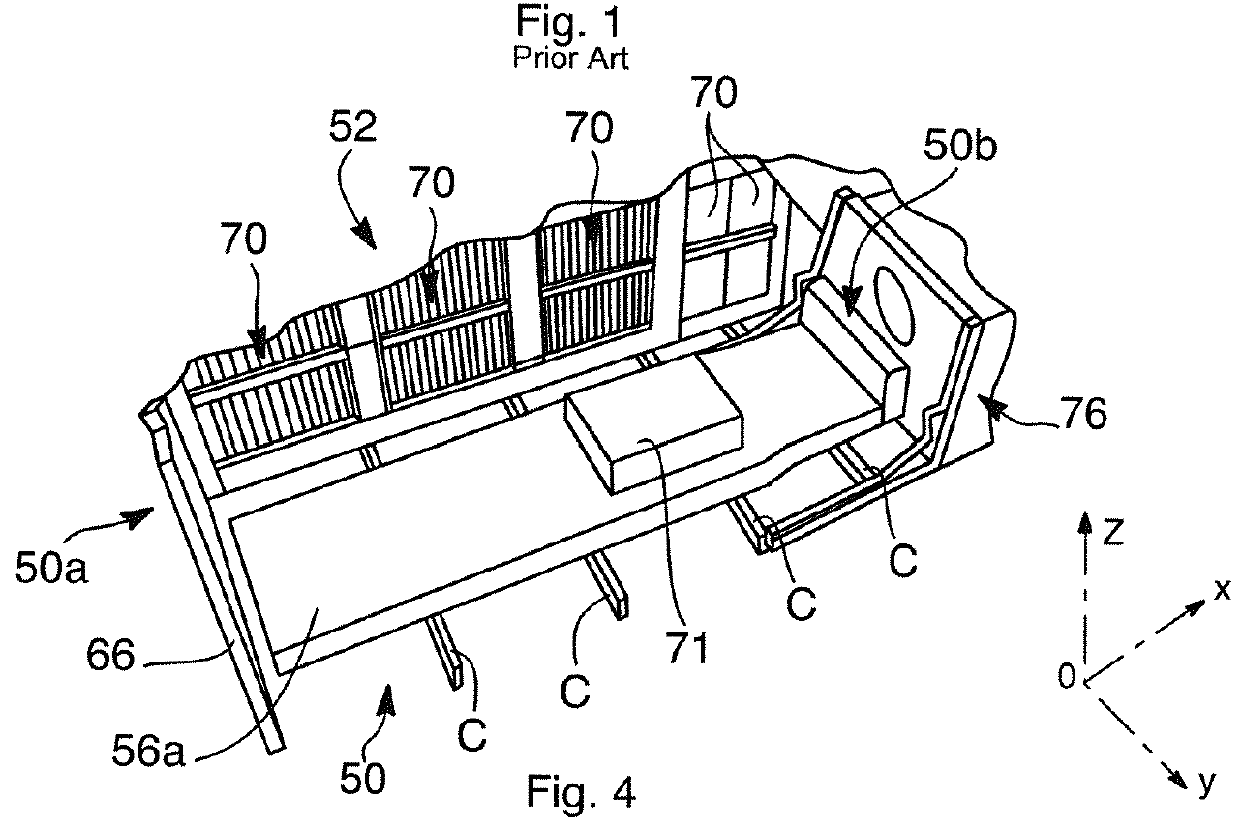
[0073]As shown from different viewpoints in FIGS. 2 and 3, an avionics bay module 50 in an embodiment of the invention is made in the form of an avionics bay structure.

[0074]In general, this avionics bay structure comprises a plurality of elements fastened together so as to form an assembly that is suitable for being moved as a unit. The elements are connected or assembled together so as to confer mechanical cohesion to the assembly enabling it to be handled as a single physical object or entity.

[0075]More particularly, the avionics bay structure includes integrated in the module specifically all of the racks for receiving the various pieces of electrical and / or electronic equipment (electrical master boxes, computers, . . . ) dedicated to the avionics bay, and also most of the equipment mounted on those racks (a predetermined number of pieces of equipment as defined in advance when designing the module), the interconnections between these pieces of equipment, and also ventilation s...


PUM

PropertyMeasurementUnit
angleaaaaaaaaaa
heightaaaaaaaaaa
flexibleaaaaaaaaaa

Abstract

An integral avionics bay module. The module has a structure that has an integral cabin floor on top that closes the structure. Installing such an integral avionics bay structure in a single operation inside a primary fuselage structure considerably reduces the integration time on the final assembly line for the aircraft.

Description

CROSS-REFERENCES TO RELATED APPLICATIONS[0001]This application claims the benefit of the French patent application No. 1262592 filed on Dec. 21, 2012, the entire disclosures of which are incorporated herein by way of reference.BACKGROUND OF THE INVENTION[0002]The invention relates to an avionics bay module, to an aircraft nose incorporating such a module, and to a method of integrating such a nose.[0003]FIG. 1 shows a nose of a prior art aircraft 10, which nose includes a primary fuselage structure 12.[0004]The primary structure 12 comprises in particular a plurality of fuselage frames 14 arranged parallel to one another along the longitudinal axis X of the nose. Only the top portions of the fuselage frames 14 are shown for reasons of clarity.[0005]The structure 12 also has a well 18 for storing the nose landing gear (not shown) of the aircraft.[0006]The primary fuselage structure 12 defines a space inside the structure that is to be fitted out.[0007]More particularly, a cabin floor...

Claims


Application Information

Patent Timeline
Patent Type & Authority Patents(United States)
IPC IPC(8): B64C1/00B64D43/00B64C1/18B64F5/00
CPCB64D43/00B64C1/18B64F5/0009B64C2001/009Y10T29/49826B64F5/10
Inventor DURAND, YVESGUERING, BERNARD
Owner AIRBUS OPERATIONS (SAS)
Why Eureka
Try Eureka