Bit-Rate Discrimination Method and Its Apparatus

a bit-rate discrimination and bit-rate technology, applied in the field of bit-rate discrimination methods and bit-rate discrimination apparatuses, can solve the problems of bit-rate changes and the inability to discriminate at high speed, and achieve the effect of reducing the integration tim

Active Publication Date: 2011-09-22
NIPPON TELEGRAPH & TELEPHONE CORP
View PDF42 Cites 7 Cited by
  • Summary
  • Abstract
  • Description
  • Claims
  • Application Information

AI Technical Summary

Benefits of technology

[0056]According to the first to ninth aspects of the invention, unlike the conventional circuit that makes the discrimination by integrating the logical code that includes “0” and “1” produced from the random code to some extent, the bit-rate is discriminated by utilizing the periodicity of the known preamble signal added to the head portion of the signal when the bit-rate of the signal is changed. More specifically, the repetition of the identical pattern is converted into a very long consecutive “1” signal (having a length of several tens of bits to several thousand bits). Although the consecutive identical signal is longer than the same-code continuation length included in the signal, the consecutive identical signal is shorter than the time constant necessary for the conventional circuit by about one to three orders of magnitude. Therefore, the integration time can be shortened to the same degree as the generated consecutive identical signal length, and the bit-rate can be discriminated at high speed within a preamble signal receiving time.
[0057]The tenth aspect of the invention can provide the bit-rate discrimination apparatus and the bit-rate discrimination method, which can automatically discriminate the bit-rate of the input signal, and the signal discriminator and the optical signal receiving discriminator, which include the bit-rate discrimination apparatus. The tenth aspect of the invention can realize the optical communication receiving apparatus that can correct the malfunction of the bit-rate discrimination circuit, instantaneously discriminate the bit-rate of the input signal even for the plural bit-rates that do not have the relationship of the integral multiple of integral fraction, and individually output the signals having the desired bit-rates from the output ports.

Problems solved by technology

As described above, because it takes a long time for the bit-rate discrimination circuits of Patent Document 1 and Patent Document 2 to make discrimination, the bit-rate cannot be discriminated at high speed in a signal transmission method in which the bit-rate changes at high speed with time.
Therefore, unfortunately the output result from the low-bit-rate discrimination circuit 113 that discriminates the low bit-rate occasionally becomes false discrimination result depending on a light intensity level of the discriminated low bit-rate.

Method used


Image

  • Bit-Rate Discrimination Method and Its Apparatus
  • Bit-Rate Discrimination Method and Its Apparatus
  • Bit-Rate Discrimination Method and Its Apparatus

Examples


first embodiment

[0105]A first embodiment of the invention will be described with reference to the accompanying drawings. The first embodiment described below is examples of the invention, and the invention is not limited to the examples. In the first embodiment and the drawings related to the first embodiment, the same component is denoted by the same numeral.

first example

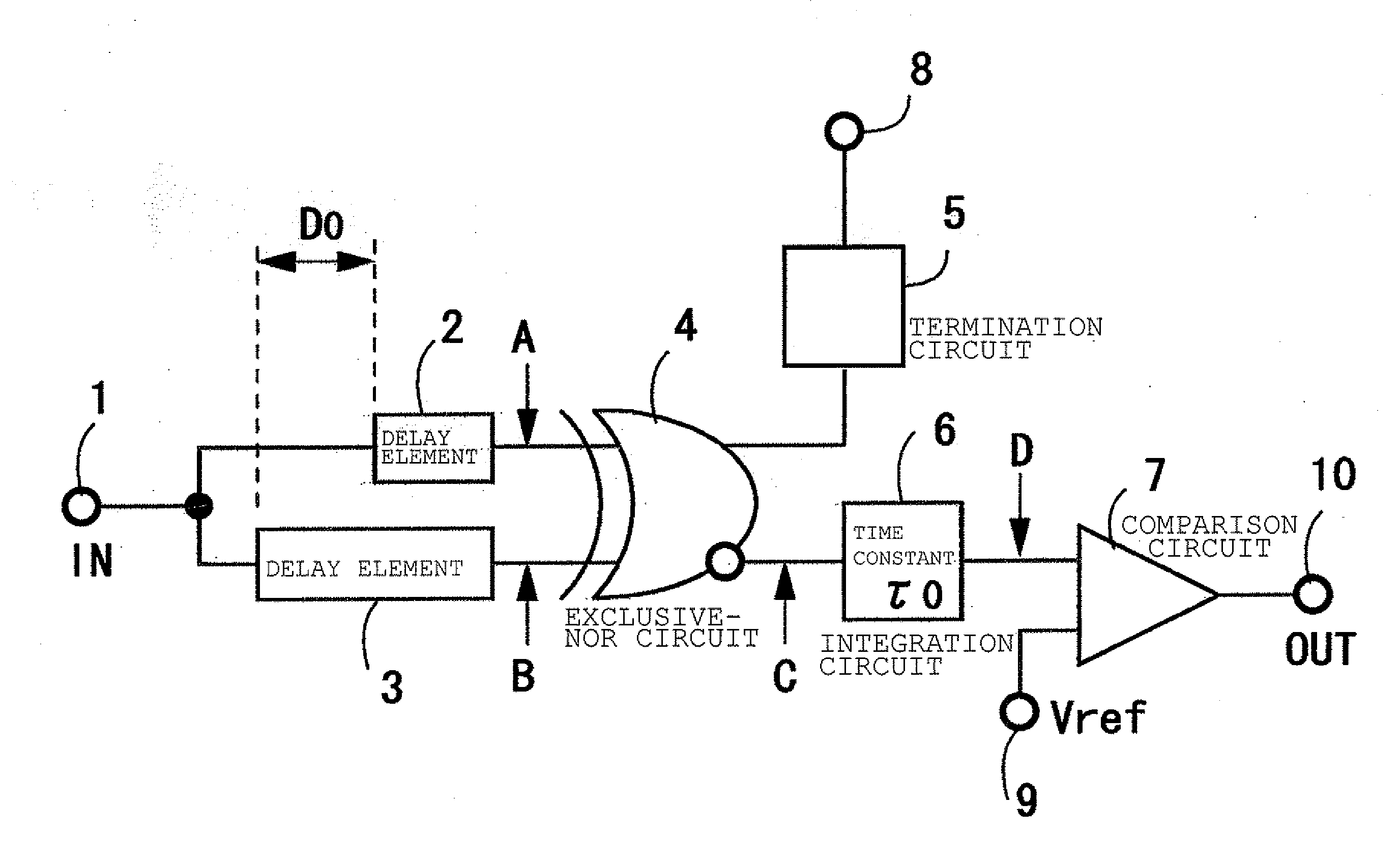
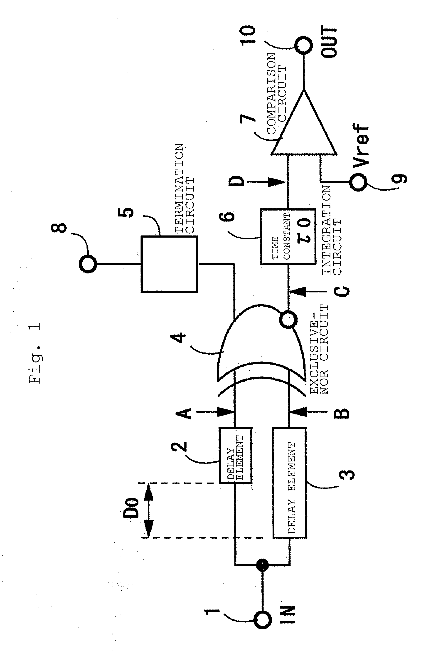
[0106]FIG. 1 illustrates a configuration of a bit-rate discrimination circuit according to a first example of the invention. Referring to FIG. 1, the numeral 1 denotes an input terminal, the numerals 2 and 3 denote delay circuits, the numeral 4 denotes an exclusive-NOR circuit, the numeral 5 denotes a termination circuit, the numeral 6 denotes an integrator (time constant of τ0), the numeral 7 denotes a comparator, the numeral 8 denotes a power supply or a ground, the numeral 9 denotes a reference voltage input terminal, and the numeral 10 denotes an output terminal (alphabets in FIG. 1 are described in the description of FIG. 2). For the sake of convenience, in the first example, it is assumed that there are two kinds of bit-rates, that is, a high rate and a low rate, in the transmitted signal.

[0107]In the delay circuits 2 and 3 connected to nodes A and 9 of the exclusive-NOR circuit 4, a delay time difference between the delay circuits 2 and 3 is adjusted to a length of an integra...

second example

[0112]FIG. 3 illustrates a configuration of a bit-rate discrimination circuit according to a second example of the invention. In FIG. 3, the component similar to that of FIG. 1 is denoted by the same numeral, the numerals 11 and 12 denote delay circuits, and the numeral 13 denotes an integrator (time constant τ1). In the second example, it is also assumed that there are two kinds of bit-rates, that is, the high rate and the low rate, in the transmitted signal. The configuration of FIG. 3 differs from that of FIG. 1 only in that the delay time difference between the delay circuits 11 and 12 is adjusted to a length of an integral multiple of the preamble pattern period of the low bit-rate signal. For the sake of convenience, the delay circuits 11 and 12 are connected in FIG. 3. When the delay of one of the delay circuits is equal to the length of the integral multiple, only one of the delay circuits may be provided. In FIG. 3, the input-side terminals of the delay circuits 11 and 12 a...


PUM


Abstract

In the present invention, unlike a conventional circuit, discrimination is not made by integrating a logical code that includes “0” and “1” to some extent and produced from a random code, but repetition of an identical pattern of a well-known preamble signal added to a head portion of a signal is discriminated when a bit-rate of the signal is changed. More specifically, the repetition of the identical pattern is converted into a consecutive identical signal to generate the consecutive identical signal (having a length of tens bits to thousands bits). Although the consecutive identical signal is longer than a same-code continuation length included in the signal, and is shorter than a time constant necessary to the conventional circuit by about one to three digits. Therefore, an integration time can be shortened to the same degree as the generated consecutive identical signal length, and the bit-rate can be discriminated at high speed within a preamble signal receiving time.

Description

TECHNICAL FIELD[0001]The present invention relates to a bit-rate discrimination method and a bit-rate discrimination apparatus for automatically discriminating a bit-rate of an input signal.BACKGROUND ART[0002]Although communication carriers provide various bit-rate services with the spread of the Internet, maintenance and operation cost increases because a different transmission device is used in each bit-rate. There is a demand for unifying the transmission devices in order to prevent the cost increase. There has been proposed a transmission device that can deal with plural bit-rates to discriminate the bit-rate inside the device (Patent Document 1), and there has also been proposed a mechanism in which optical receiver sensitivity is varied according to the bit-rate (Patent Document 2).[0003]A bit-rate discrimination circuit that discriminates the bit-rates is roughly classified into two type methods. In one of the methods, an edge portion (logical code switching portion of “0” / “...

Claims


Application Information

Patent Timeline
Patent Type & Authority Applications(United States)
IPC IPC(8): H04B10/06
CPCH04L25/0262
Inventor HARA, KAZUTAKAKIMURA, SHUNJINAKAMURA, HIROTAKAKITAHARA, KOJIURABE, YOSHIKAZUENDO, MASAHIRO
Owner NIPPON TELEGRAPH & TELEPHONE CORP
Why Eureka
Try Eureka