Control method for the AGC unit of a radio receiver

a control method and radio receiver technology, applied in the direction of transmission monitoring, instruments, wireless commuication services, etc., can solve the problems of inflexible control process in different environments, no such convergence response can be guaranteed, etc., and achieve the effect of shortening the integration time of the power calculation uni

a control method and radio receiver technology, applied in the direction of transmission monitoring, instruments, wireless commuication services, etc., can solve the problems of inflexible control process in different environments, no such convergence response can be guaranteed, etc., and achieve the effect of shortening the integration time of the power calculation uni

US20050064834A1Inactive Publication Date: 2005-03-24INFINEON TECH AG

Image

  • Control method for the AGC unit of a radio receiver
  • Control method for the AGC unit of a radio receiver
  • Control method for the AGC unit of a radio receiver

Examples


Embodiment Construction

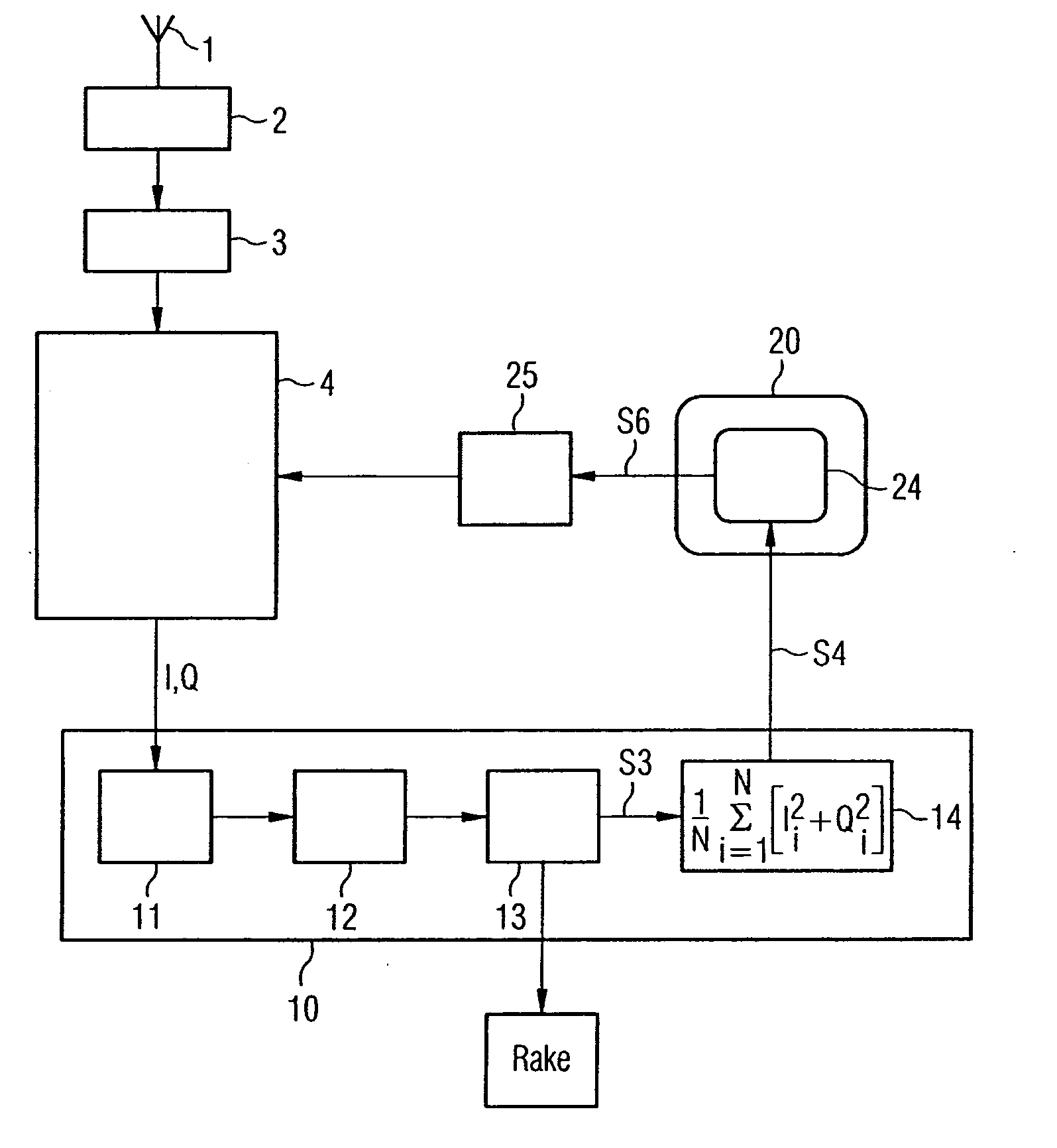
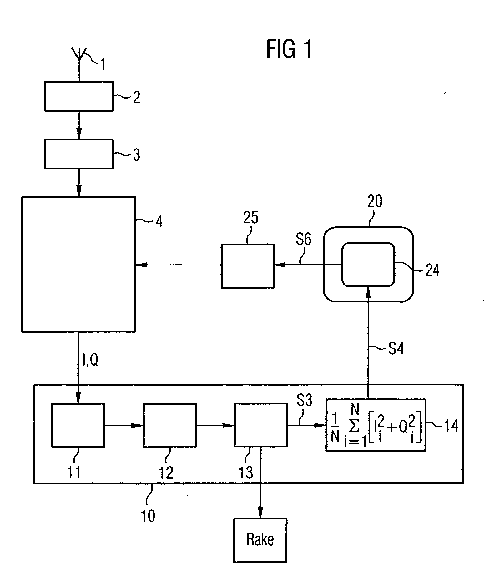
FIG. 1 shows the AGC unit in the receiving section of a UMTS radio receiver. The signals which are received at the antenna 1 are passed via different analogue components such as an antenna switch 2 and a low-noise amplifier 3 to the radio-frequency unit 4, where they are normalized, amplified again and down-mixed to baseband. The signal is sampled by analogue / digital converter 11. A digital filter chain 12 and an RRC filter (root raised cosine) 13 limit the digital signal to a specific bandwidth in accordance with the UMTS Standard. A power calculation unit 14 averages the power of this bandwidth-limited signal S3 over a defined time period. The power calculation unit 14 is in this case in the form of dedicated hardware. The measured value S4 is passed to a digital signal processor (DSP) 20, in which the control algorithm 24, which is implemented in firmware, calculates a new manipulated variable S6. The manipulated variable S6 is passed via a radio-frequency interface 25 to the rad...


PUM


Abstract

In a method for determination of controller settings for a control loop for controlling the reception signal strength of a radio receiver, the transfer function for that part of the signal path of the radio receiver which forms the controlled section (4, 10) of the control loop is known at least approximately as a function. The controller settings are determined by calculation, by optimization of the overall transfer function of the control loop with respect to a desired optimality criterion, taking into account the known function.

Description

PRIORITY This application claims priority to German application no. 103 44 089.5 filed Sep. 23, 2003. TECHNICAL FIELD OF THE INVENTION The present invention relates to a method for controlling the regulation of the reception signal strength in a mobile radio receiver. In mobile radio systems, the signals are transmitted on radio paths with different propagation characteristics, so that the received signal strength at the antenna of the mobile receiver is subject to considerable fluctuations. By way of example, the 3GPP Standard for UMTS FDD (Universal Mobile Telecommunications System, Frequency Division Duplex) specifies, in Technical Specification 25.101, a received signal strength fluctuation from −25 dBm to −106.7 dBm at the antenna, that is to say a range of more than 80 dB, or more than four orders of magnitude. It is advantageous to counteract these major fluctuations in the reception signal strength even before the signal is sampled by the analogue / digital converter in the...

Claims


Application Information

Patent Timeline
24 Mar 2005
Publication
US20050064834A1
IPC
H03G3/30; H04B17/00
CPC
H04B17/318; H03G3/3036
Inventors
BILGIC, ATTILA