Current detection apparatus

a detection apparatus and current technology, applied in resistance/reactance/impedence, electrochemical generators, instruments, etc., can solve the problems of less than 100% solder fill, poor solder rise, mechanical fatigue strength reduction, etc., to prevent an increase in product size and determine visibly with ease

Active Publication Date: 2016-06-07
DENSO CORP
View PDF12 Cites 2 Cited by
  • Summary
  • Abstract
  • Description
  • Claims
  • Application Information

AI Technical Summary

Benefits of technology

[0011]According to the embodiment, the open end of the recessed portion of the casing that can be engaged with the cover (also referred to as an engagement section of the recessed portion) is non-parallel to the circuit board so that the upper end portion of the circuit board including the solder junction lies outside of the recessed portion, thereby allowing a soldered condition of the solder junction to be determined visibly with ease. In addition, only the portion of the circuit board including the solder junction is allowed to lie outside of the recessed portion of the casing and the whole circuit board doesn't have to be raised above the level of the open end of the recessed portion of the casing when mounted on the battery, thus preventing an increase in product size.

Problems solved by technology

Unsuitable selection of a soldering condition or a flux material may lead to poor solder rise, i.e., less than 100% solder fill, as a kind of soldering failure.
In the case of poor solder rise, a shortage of solder junction area may reduce thermal fatigue resistance and mechanical fatigue strength under heavy vibration at the solder junction.
In the disclosed apparatus, however, the circuit board lies lower than the level of a cover-mounting surface of the casing, and a clearance between the circuit board and an inside wall of the casing is small.
This solution, however, leads to an increase in product size.
Therefore, the increase in product size, which may reduce mountability in the engine compartment and maintainability of the vehicle, is not desirable.

Method used


Image

  • Current detection apparatus
  • Current detection apparatus
  • Current detection apparatus

Examples


Embodiment Construction

[0028]The present inventions will be described more fully hereinafter with reference to the accompanying drawings. Like numbers refer to like elements throughout.

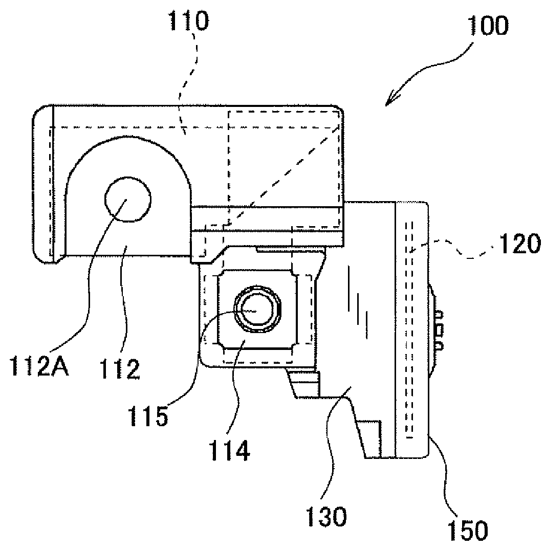
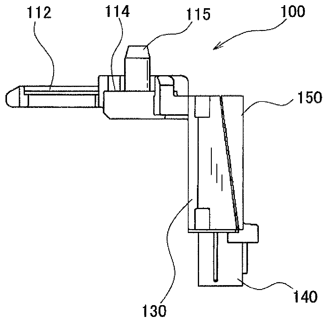
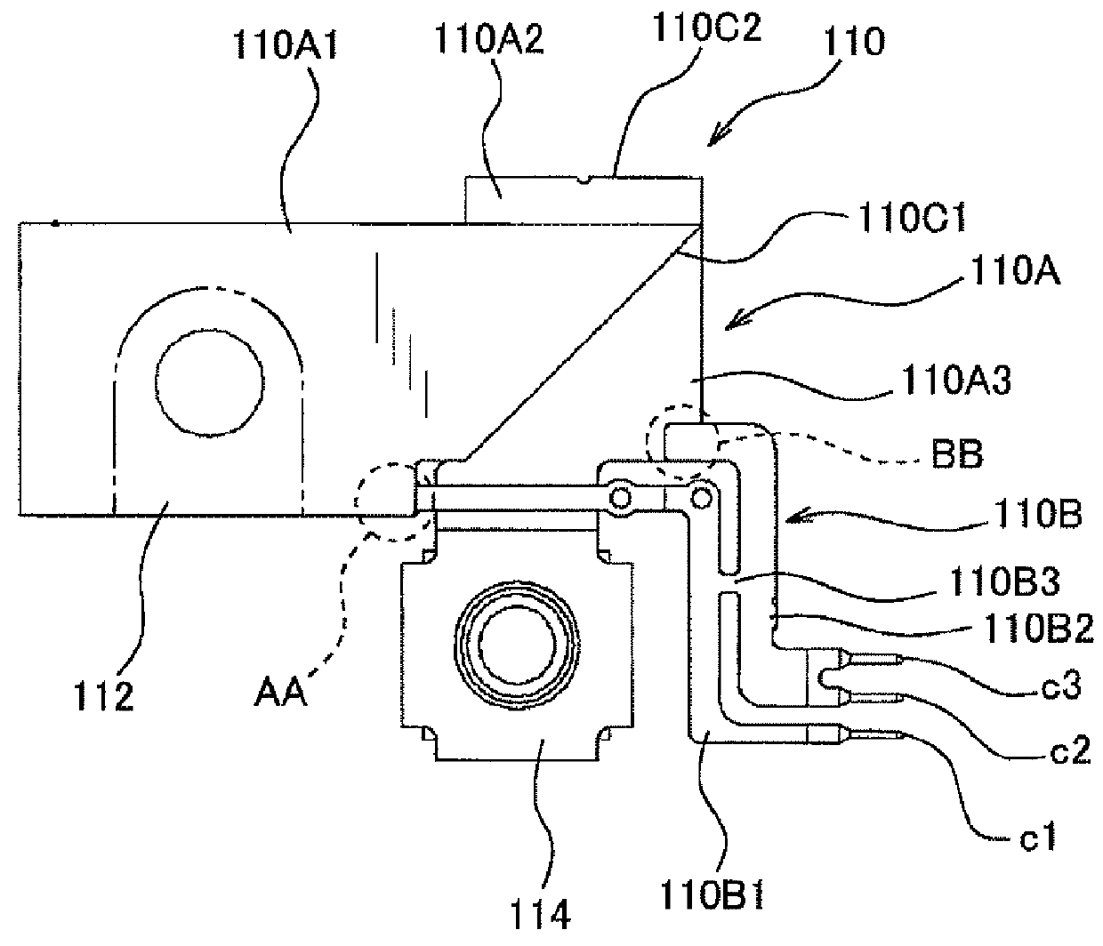
[0029]FIG. 1 is a top view of a current detection apparatus in accordance with one embodiment of the present invention. FIG. 2 is a side view of the current detection apparatus, taken from below FIG. 1. FIG. 3 is a side view of the current detection apparatus, taken from right of FIG. 1.

[0030]The current detection apparatus 100 of the present embodiment includes a bus bar 110 serving as a resistor (referred to as a shunt resistor) formed from a conductive material, a circuit board 120 provided thereon with a current detection circuit that detects a current flowing through the bus bar 110 on the basis of a potential difference between two positions along a current carrying path of the bus bar 110, a casing 130 housing the bus bar 110 and the circuit board 120, a connector 140 having a plurality of connector terminals exposed...


PUM

PropertyMeasurementUnit
specific angleaaaaaaaaaa
currentaaaaaaaaaa

Abstract

A current detection apparatus for detecting a current from a battery flowing through a harness. The apparatus includes a resistor having a current carrying member disposed between a terminal of the battery and the harness, a circuit board provided thereon with a current detection circuit for detecting a current flowing through the resistor, and a casing having a recessed portion for accommodating the circuit board, a cover for closing an opening of the recessed portion. The circuit board includes a solder junction between the circuit board and a terminal protruding from an inside bottom of the recessed portion and passing through a through hole arranged on the circuit board, and an open end of the recessed portion that can be engaged with the cover is non-parallel to the circuit board so that at least a portion of the circuit board including the solder junction lies outside of the recessed portion.

Description

CROSS-REFERENCE TO RELATED APPLICATION[0001]This application is based on and claims the benefit of priority from earlier Japanese Patent Application No. 2011-238471 filed Oct. 31, 2011, the description of which is incorporated herein by reference.BACKGROUND[0002]1. Technical Field[0003]The present invention relates to a current detection apparatus mounted in a vehicle, such as a passenger car or a truck, for detecting a charge or discharge current of a battery.[0004]2. Related Art[0005]A known current detection apparatus, as disclosed in Japanese Patent No. 2704483, includes a circuit board (in the form of a printed-circuit board) provided with an electronic circuit thereon, and a casing accommodating the circuit board therein with a cover closing an opening of the casing to form an enclosure. In this current detection apparatus, each of a plurality of contact pins protruding from an inside surface of the casing and passing through a respectively corresponding through-hole arranged ...

Claims


Application Information

Patent Timeline
Patent Type & Authority Patents(United States)
IPC IPC(8): G01R27/08G01R31/36H01M10/48H01R11/28
CPCG01R31/3696H01M10/48H01R11/287G01R31/364Y02E60/10
Inventor KIKUCHI, TSUKASA
Owner DENSO CORP
Why Eureka
Try Eureka