Method for forming film by plasma-assisted deposition using two-frequency combined pulsed RF power

a plasma-assisted deposition and dielectric film technology, applied in chemical vapor deposition coatings, coatings, electric discharge tubes, etc., can solve problems such as expansion, cracking, and air gap structures subject to defects, and achieve the effect of film quality

Active Publication Date: 2016-06-14
ASM IP HLDG BV
View PDF7 Cites 329 Cited by
  • Summary
  • Abstract
  • Description
  • Claims
  • Application Information

AI Technical Summary

Benefits of technology

[0008]In some embodiments of the present invention, by using two-frequency combined pulsed RF power wherein the RF power is comprised of pulses of high-frequency RF power and pulses of low-frequency RF power, wherein the pulses of high-frequency RF power and the pulses of low-frequency RF power overlap and are synchronized, a step coverage of film can be improved in both an area where the distance between lines is narrow and an area where the distance between lines is wide, and a film formed on sidewalls of patterned recesses can become dense and the film quality can be improved, rendering less difference in film properties between the film formed on the top surface and the film formed on the sidewalls. In some embodiments, the wet etch rate of the film formed on the sidewalls is equivalent to or lower than that of the film formed on the top surface.

Problems solved by technology

When the films formed on sidewalls are porous films having high degassing, the air-gap structures are subject to defects such as expansion, cracking, etc. during subsequent processes using high temperature such as film deposition processes and CMP processes.

Method used


Image

  • Method for forming film by plasma-assisted deposition using two-frequency combined pulsed RF power
  • Method for forming film by plasma-assisted deposition using two-frequency combined pulsed RF power
  • Method for forming film by plasma-assisted deposition using two-frequency combined pulsed RF power

Examples


example 1

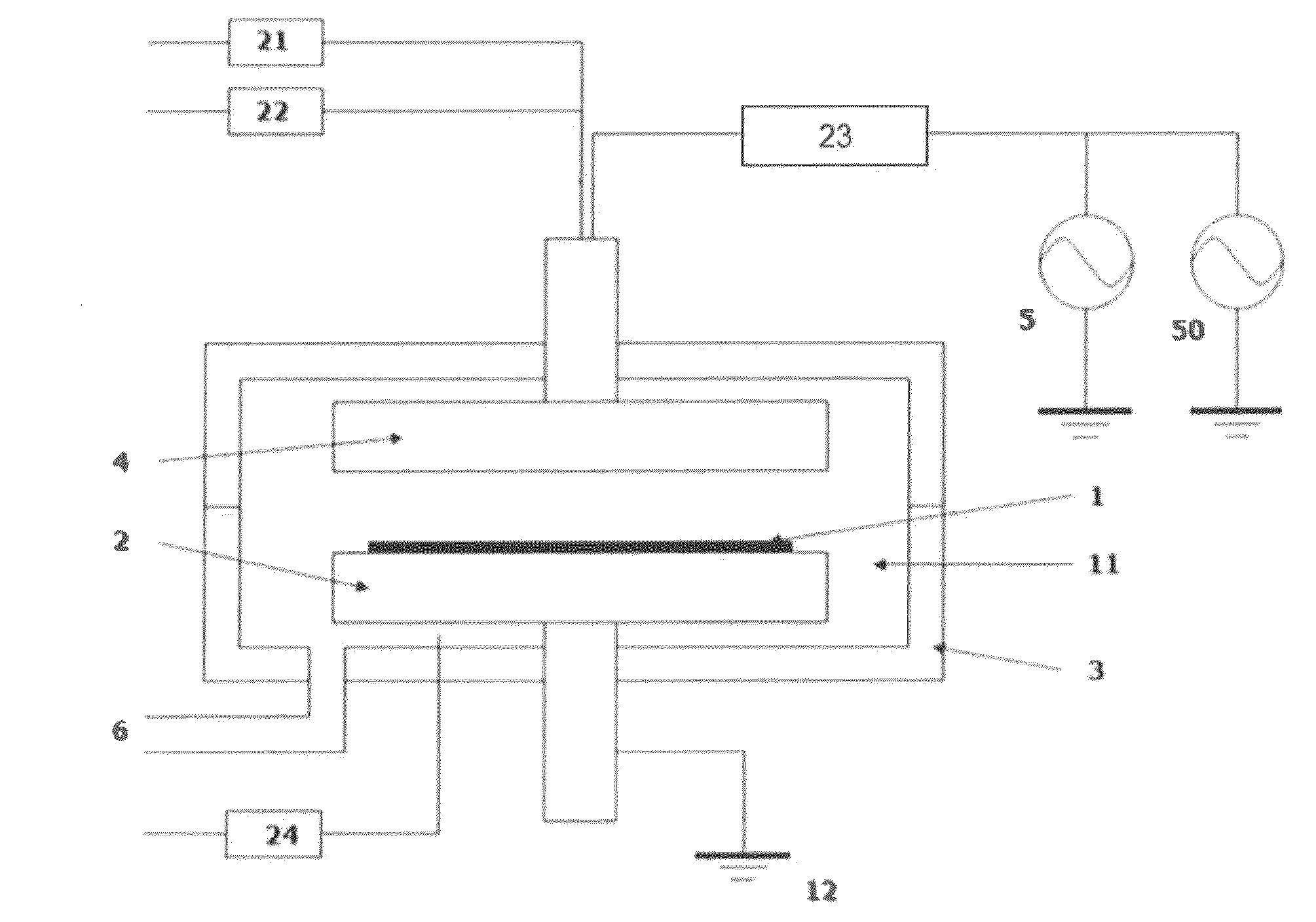
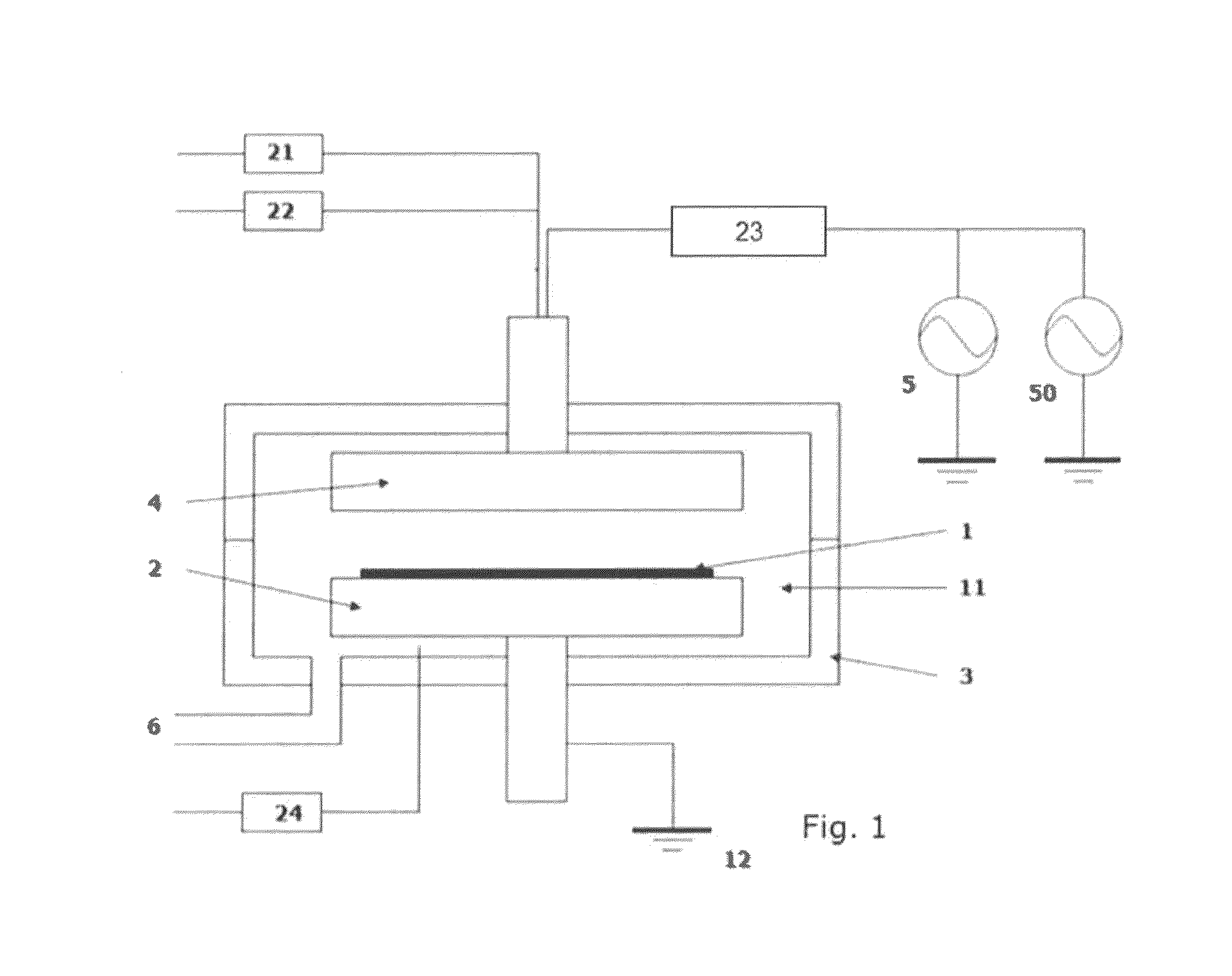
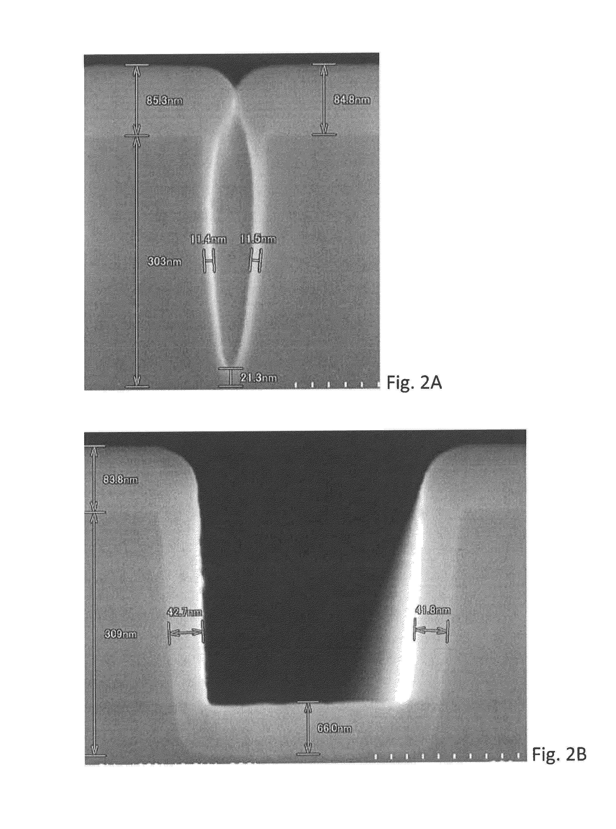
[0062]A dielectric film was formed on a 300-mm substrate having a patterned surface having an aspect ratio of 3.4 and an aspect ratio of 0.8 and an opening width of approximately 50 nm and approximately 230 nm, respectively, under the conditions shown below using the PECVD apparatus illustrated in FIG. 1. HRF and LRF pulse patterns were set as illustrated in (a) of FIG. 6 (100% overlap).[0063]Precursor: SiH4 [0064]Precursor inflow pressure: 300 Pa[0065]Precursor flow (continuous): 100 sccm[0066]Additive gas: N2O[0067]Additive gas flow (continuous): 4,000 sccm[0068]Substrate temperature: 400° C.[0069]HRF frequency: 13.56 MHz[0070]HRF power: 300 W[0071]LRF frequency: 430 kHz[0072]LRF power: 300 W[0073]HRF / LRF ON time: 0.3 milliseconds (Duty ratio: 30%)[0074]HRF / LRF OFF time: 0.7 milliseconds (Cycle: 1.0 milliseconds)[0075]Deposition time: 0.5 minutes

[0076]As a comparative example, a film was formed under the same conditions except that HRF and LRF powers were continuously applied with...

example 2

[0080]A film was formed in a patterned recess having an aspect ratio of 3.4 (AR3.4) of a substrate under the conditions which were the same as in Example 1 except that the duty ratio and the cycle (a period of one cycle) of HRF and LRF were adjusted as shown in Table 2 below. The step coverage (S / C) of each resultant film is shown in Table 2.

[0081]

TABLE 2Step CoverageRF-Duty Ratio [%]Cycle [msec]103050100cont.13.5%10—20.9%—13.5%2—20.0%—13.5%121.9%18.9%18.3%13.5%0.5—19.0%—13.5%0.1—14.7%—13.5%

[0082]As can be seen in Table 2, the step coverage was improved when using the two-frequency combined pulsed RF power, wherein the longer the cycle, and the smaller the duty ratio, the higher the step coverage improvement became.

example 3

[0083]A film was formed in a patterned recess having an aspect ratio of 3.4 (AR3.4) of a substrate under the conditions which were the same as in Example 1. The obtained film was analyzed with respect to wet etch resistance (etch rate (nm / min) when dipped in a solution of 130 BHF for 60 seconds) of a section of the film deposited on a top surface of the substrate, and of a section of the film deposited on sidewalls. The results are shown in Table 3.

[0084]

TABLE 3Δ130BHF (Dip Time 60 sec)TopSideSide / Top[nm][nm]RatioHRF / LRF cont.16.722.21.33HRF / LRF pulse25.321.40.84

[0085]As can be seen in Table 3, when the two-frequency combined continuous RF power was used, the film formed on the top surface was hard whereas the film formed on the sidewalls was soft, and thus, the ratio of top wet etch rate to side wet etch rate was as high as 1.33, indicating that the side film was etched significantly faster than the top film. In contrast, when the two-frequency combined pulsed RF power was used, th...


PUM

PropertyMeasurementUnit
frequencyaaaaaaaaaa
frequencyaaaaaaaaaa
aspect ratioaaaaaaaaaa

Abstract

A method for forming a dielectric film on a substrate by plasma-assisted deposition, includes: introducing a Si-containing process gas to a reaction space wherein a substrate having a surface with patterned recesses is placed; and applying RF power to the process gas in the reaction space to form a dielectric film on the surface by plasma reaction. The RF power is comprised of pulses of high-frequency RF power and pulses of low-frequency RF power, which overlap and are synchronized.

Description

BACKGROUND OF THE INVENTION[0001]1. Field of the Invention[0002]The present invention generally relates to plasma-assisted deposition, in particular to a method for forming a dielectric film by plasma-assisted deposition using two-frequency combined pulsed RF power.[0003]2. Description of the Related Art[0004]As device miniaturization progresses, dielectric constants of interlayer insulation films which insulate intercalation need to be lower. Ideally, air-gap structures having a dielectric constant of one (k=1) are used. However, even with the air-gap structures, sidewalls of patterned recesses facing each other via an air gap need to be covered by an insulation film having a certain thickness. Films formed on sidewalls of patterned recesses are typically thinner than those formed on top surfaces of the recesses, but it is required that the films be stable and dense so as not to be apt to change properties with time and not to release gas to the air gaps. A SiO film is typically us...

Claims


Application Information

Patent Timeline
Patent Type & Authority Patents(United States)
IPC IPC(8): C23C16/515C23C16/04C23C16/509H01J37/32
CPCC23C16/045C23C16/5096C23C16/515H01J37/32091H01J37/32146H01J37/32165
Inventor NONAKA, YUYASHOJI, FUMITAKAARAI, HIROKI
Owner ASM IP HLDG BV
Why Eureka
Try Eureka