Optical systems for see-through displays

a technology of optical configuration and computer display, applied in the field of head-worn computing, can solve the problems of many problems persisting in the wearable computing field, and achieve the effects of low weight, comfortable wear and high quality

Active Publication Date: 2016-06-14
OSTERHOUT GROUP INC
View PDF201 Cites 152 Cited by
  • Summary
  • Abstract
  • Description
  • Claims
  • Application Information

AI Technical Summary

Benefits of technology

[0006]In displays it is typically important to provide a high quality image to the user. In head mounted displays it is important to provide a compact display assembly that is low in weight so the display can be comfortably worn on the head of the user. In head mounted displays that provide a see-through view of the environment, it is also important to provide a high contrast displayed image with black blacks so the environment can be easily viewed. Optical systems of the present inventions are small, light-weight and produce high image quality in a head-worn see-through device.
[0007]Systems and methods described herein provide upper optics comprised of a reflective display, a field lens, a reflective polarizer and a light source. The optical layout of the illumination optical path and the imaging optical path are overlapped to reduce the overall size of the optics package. In embodiments, a flat reflective polarizer is used both to redirect polarized illumination light toward a reflective image source and to act as the analyzer polarizer on the image light thereby enabling more compact optics and reducing the weight of the display assembly. In embodiments where the reflective polarizer is flat, the illumination light is provided with a central light ray at about 45 degrees, high incident angle surfaces are avoided to reduce scattered light and thereby enable increased contrast in the displayed image. Further, the flat reflective polarizer can be a film or a coating to reduce weight. Space is provided at the surface of the reflective image source so that a compensator film can be provided on the reflective image source to provide a higher contrast image to the user.
[0008]In embodiments, the lower optics comprising a beam splitter, a quarter wave film and a rotationally curved partial mirror, are largely comprised of air to provide a compact display assembly that has very low weight. In addition, in embodiments, the optical surfaces in the imaging optics are all either on axis or flat to thereby preserve the wavefront of the image light and thereby provide a high image quality.

Problems solved by technology

Many problems persist in the wearable computing field that need to be resolved to make them meet the demands of the market.

Method used


Image

  • Optical systems for see-through displays
  • Optical systems for see-through displays
  • Optical systems for see-through displays

Examples


Embodiment Construction

)

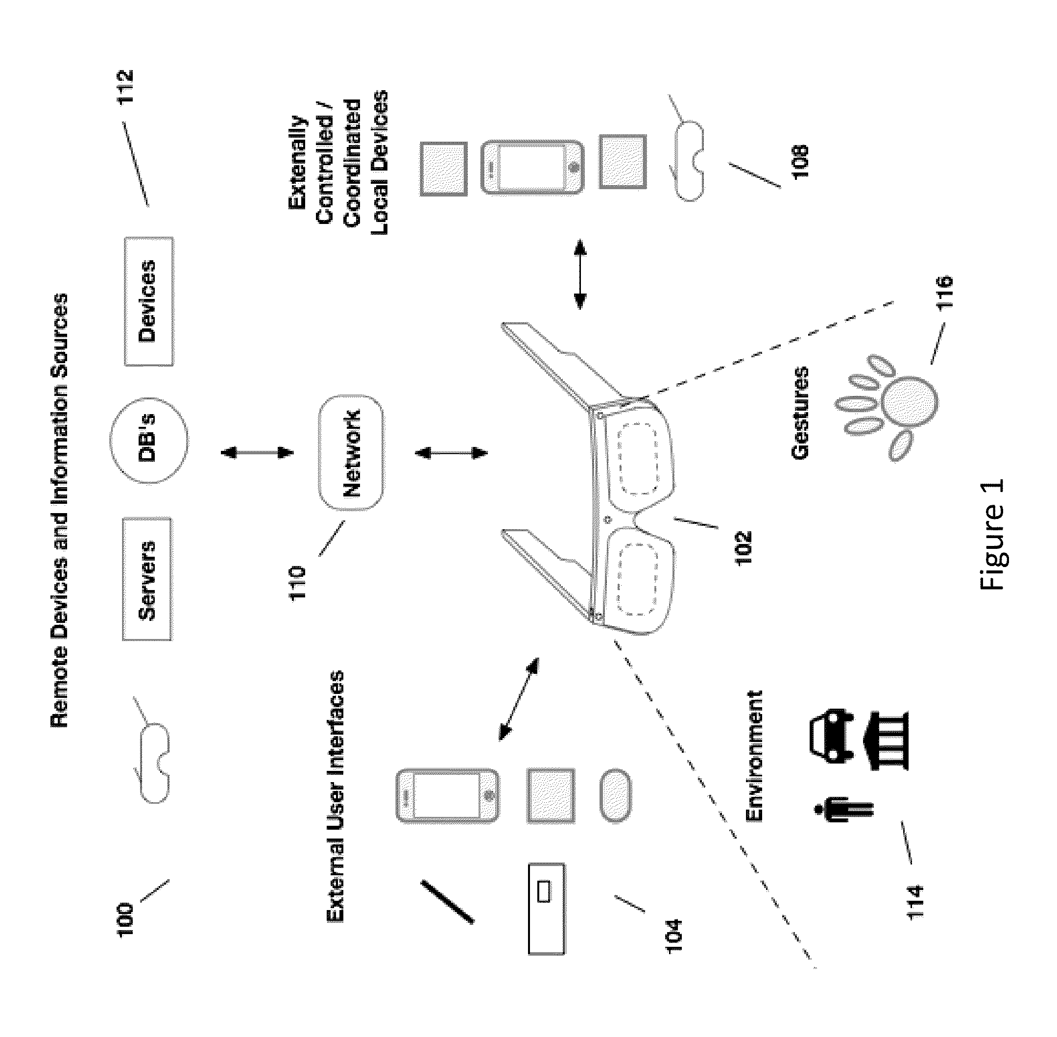
[0080]Aspects of the present invention relate to head-worn computing (“HWC”) systems. HWC involves, in some instances, a system that mimics the appearance of head-worn glasses or sunglasses. The glasses may be a fully developed computing platform, such as including computer displays presented in each of the lenses of the glasses to the eyes of the user. In embodiments, the lenses and displays may be configured to allow a person wearing the glasses to see the environment through the lenses while also seeing, simultaneously, digital imagery, which forms an overlaid image that is perceived by the person as a digitally augmented image of the environment, or augmented reality (“AR”).

[0081]HWC involves more than just placing a computing system on a person's head. The system may need to be designed as a lightweight, compact and fully functional computer display, such as wherein the computer display includes a high resolution digital display that provides a high level of emersion comprised...


PUM


Abstract

Aspects of the present invention relate to methods and systems for providing a high quality display images in see-through head-worn optics.

Description

BACKGROUND[0001]1. Field of the Invention[0002]This invention relates to head worn computing. More particularly, this invention relates to optical configurations for head-worn see-through computer displays.[0003]2. Description of Related Art[0004]Wearable computing systems have been developed and are beginning to be commercialized. Many problems persist in the wearable computing field that need to be resolved to make them meet the demands of the market.SUMMARY[0005]Aspects of the present invention relate to optical configurations for head-worn see-through computer displays.[0006]In displays it is typically important to provide a high quality image to the user. In head mounted displays it is important to provide a compact display assembly that is low in weight so the display can be comfortably worn on the head of the user. In head mounted displays that provide a see-through view of the environment, it is also important to provide a high contrast displayed image with black blacks so t...

Claims


Application Information

Patent Timeline
Patent Type & Authority Patents(United States)
IPC IPC(8): G02B27/14G09G5/00G02B27/01G02B27/28
CPCG02B27/0172G02B27/28G02B5/30G02B2027/0178G02B2027/0118G02B27/0176G02B27/283G02B2027/0152
Inventor BORDER, JOHN N.BIETRY, JOSEPHHADDICK, JOHN D.
Owner OSTERHOUT GROUP INC
Why Eureka
Try Eureka