
Drive control device

a technology of control device and drive, which is applied in the direction of electric programme control, program control, instruments, etc., can solve the problems of program debugging failure, high cost and feasible configuration, and failure of the program called “hidden bug” to occur, etc., to achieve high efficiency program development environment and low cost.

Active Publication Date: 2016-06-14
RISO KAGAKU CORP
View PDF11 Cites 0 Cited by
  • Summary
  • Abstract
  • Description
  • Claims
  • Application Information

AI Technical Summary

Benefits of technology

The invention is a drive control device that has multiple safety functions, including fail-safe functions that can be easily detected and addressed by software. Additionally, the device allows for efficient programming and debugging without the need for excessive safety measures. These features provide a simpler, more cost-effective, and feasible solution for ensuring safety in drive control.

Problems solved by technology

However, during development of a program of an embedded microcontroller, such as those described above, a situation where operation of the program has to be suspended for the purpose of debug often occurs.
In such a situation, if the operation is suspended in a state where electricity is applied to the actuator, damage due to a mechanical section being locked and / or abnormal heating due to application of excessive electricity may occur.
Further, with respect to embedded microcontrollers, a failure of the program called “hidden bug” may occur, which is a factor of malfunction that may hinder normal operation of the program in not a few cases.
The above-described locked mechanical section and / or abnormal heating may also occur due to such abnormal operation of the program.
In the case where the rotational speed of the motor becomes inconstant, paper jam may occur in a paper transport system, or gear tooth chipping, belt breakage, shaft bending, etc., may occur due to a mechanism system being locked, for example.
In some cases, the power system device may be damaged due to the motor being locked.
If the suspension or abnormal operation of the program, as described above, occurs in a drive control system that makes a reciprocating motion within a limit position range, as shown in FIG. 23, the drive control system may not be able to perform recovery operation by itself after recovery of the program to normal operation due to the mechanism system being locked.
In some cases, the user may be injured or the power system device may be damaged due to the motor being locked, as described above.

Method used


Image

  • Drive control device
  • Drive control device
  • Drive control device

Examples


first embodiment

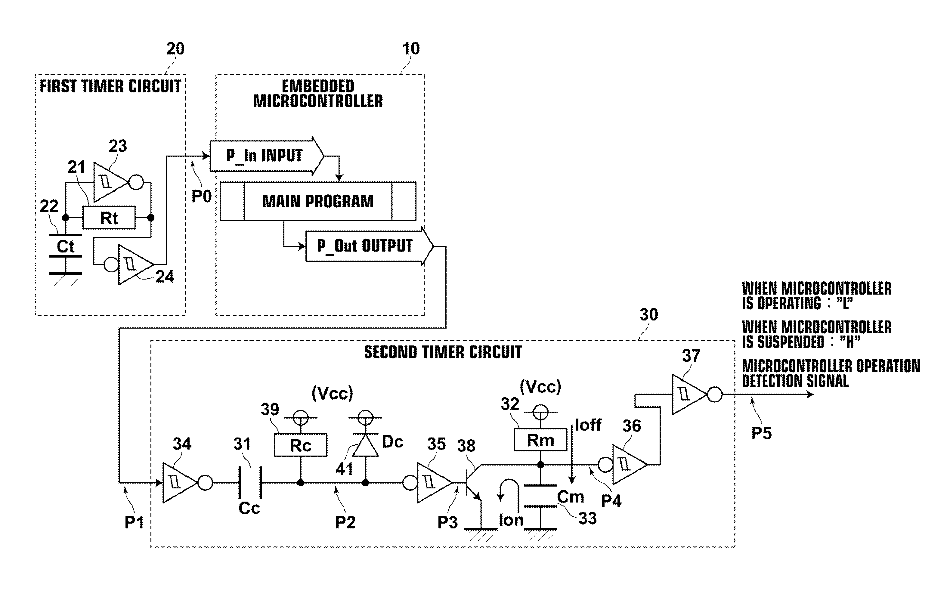
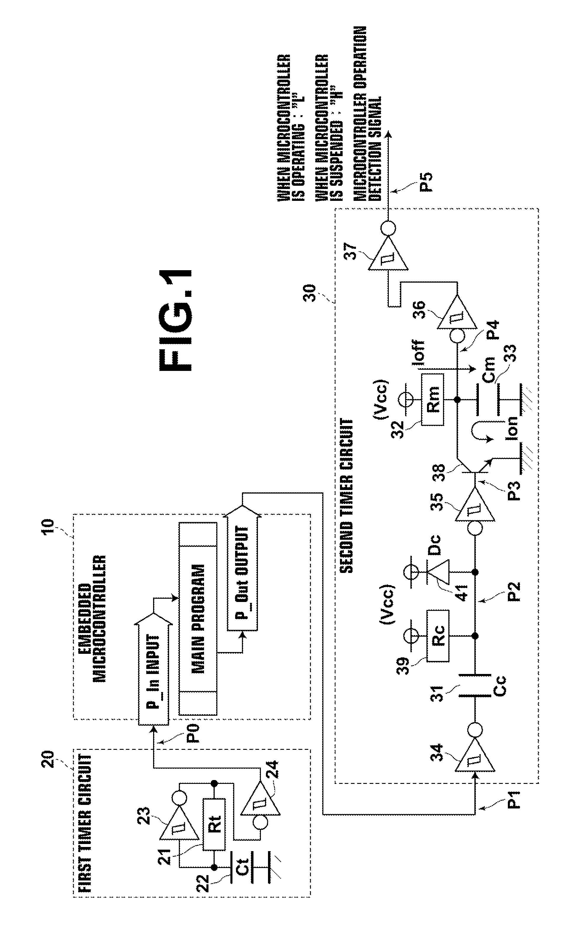
[0055]Hereinafter, a drive control device of the present invention will be described in detail with reference to the drawings. The drive control device of this embodiment includes an embedded microcontroller, which outputs a drive control signal to a driving unit that drives an apparatus having a mechanical mechanism, a display device, or the like. In particular, the drive control device is adapted to be able to ensure safety in the event of abnormal operation of a program included in the embedded microcontroller. FIG. 1 is a block diagram illustrating the schematic configuration of the entire drive control device of this embodiment.

[0056]As shown in FIG. 1, the drive control device of this embodiment includes an embedded microcontroller 10, a first timer circuit 20 and a second timer circuit 30.

[0057]The embedded microcontroller 10 is formed, for example, by a CPU (Central Processing Unit) or a DSP (Digital Signal Processor), and includes a main program for outputting a drive contr...

second embodiment

[0089]As shown in FIG. 9, the drive control device of the second embodiment includes an embedded microcontroller 40, a first timer circuit 50, and a second timer circuit 60.

[0090]Each of the first timer circuit 50 and the second timer circuit 60 of this embodiment is formed by a retriggerable monostable multivibrator and their function is equivalent to that of the second timer circuit 30 of the above-described first embodiment. Namely, similarly to the second timer circuit 30 of the first embodiment, the first timer circuit 50 and the second timer circuit 60 provide an inverted output when no trigger is fed thereto for a given length of time, and the output state does not change until the trigger is restarted.

[0091]Similarly to the first timer circuit 20 of the first embodiment, the first timer circuit 50 outputs a cyclic signal; however, the content of the cyclic signal is different. The first timer circuit 50 of the second embodiment outputs only a signal corresponding to a half c...


PUM


Abstract

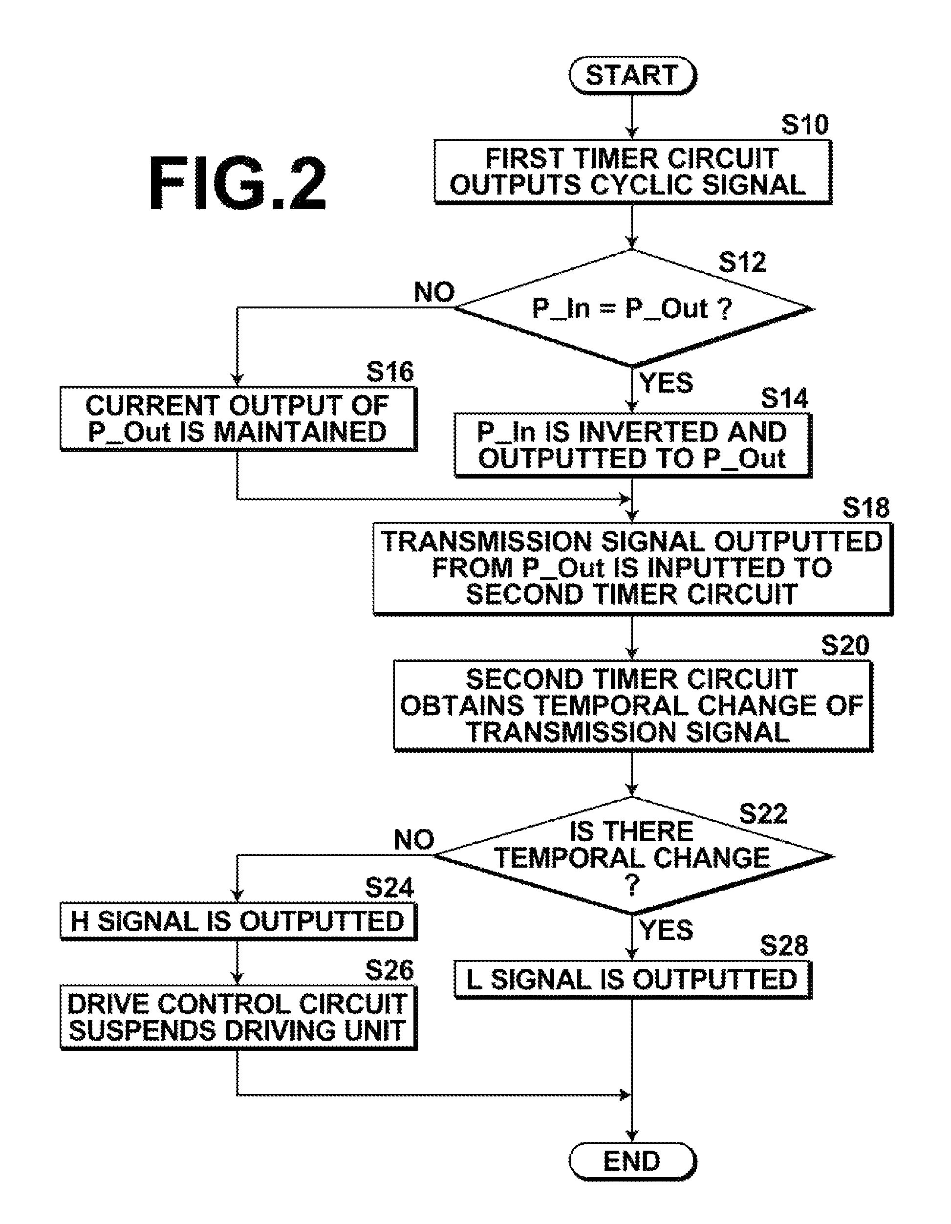
A drive control device includes: an embedded microcontroller including a program for outputting a drive control signal to a driving unit; a first timer circuit for outputting a cyclic signal to the embedded microcontroller, wherein the embedded microcontroller reads the cyclic signal outputted from the first timer circuit and transmits the cyclic signal to output a transmission signal as part of operation of the program; and a second timer circuit provided externally to the embedded microcontroller, wherein the transmission signal is inputted to the second timer circuit, the second timer circuit obtains temporal change of the transmission signal for a time set in advance, and the second timer circuit outputs, based on the obtained result, a signal indicating one of different operation states of the embedded microcontroller depending on whether or not there is continuous temporal change of the transmission signal.

Description

BACKGROUND OF THE INVENTION[0001]1. Field of the Invention[0002]The present invention relates to a drive control device including an embedded microcontroller that includes a program for outputting a drive control signal to a driving unit that drives a given apparatus.[0003]2. Description of the Related Art[0004]In recent years, in order to control movement of a given mechanical section using an actuator including a driving unit, such as a motor, an embedded microcontroller, such as a CPU (Central Processing Unit) or a DSP (Digital Signal Processor), including a program for drive control of the actuator is often used.[0005]Specifically, for example, Japanese Unexamined Patent Publication No. S61 (1986)-5504 (hereinafter, Patent Document 1) proposes using an embedded microcontroller to control an electromagnet mechanism to achieve switching between red and black ink ribbons of a serial printer. Each of Japanese Unexamined Patent Publication Nos. 2009-93014 and 2009-42595 (hereinafter,...

Claims


Application Information

Patent Timeline
Patent Type & Authority Patents(United States)
IPC IPC(8): G06F11/00G06F11/07
CPCG06F11/0757G06F11/0736G06F11/0754G05B19/02G06F11/0796G05B19/0428
Inventor SUZUKI, MASAO
Owner RISO KAGAKU CORP
Learn More