Set of rotor disks for a turbine engine

a technology of rotor disks and turbine engines, which is applied in the direction of machines/engines, sustainable transportation, mechanical equipment, etc., can solve the problems of large reduction of flanges, greatly reduced machining requirements of disks, and very high cost, and achieves simple, effective and inexpensive effects

Active Publication Date: 2016-06-21
SN DETUDE & DE CONSTR DE MOTEURS DAVIATION S N E C M A
View PDF24 Cites 3 Cited by
  • Summary
  • Abstract
  • Description
  • Claims
  • Application Information

AI Technical Summary

Benefits of technology

[0011]A particular object of the invention is to provide a solution to this problem that is simple, effective, and inexpensive.
[0013]In this way, none of the disks need have any flanges, thereby making them easier to fabricate by machining. The ferrules may be subjected to rolling using presser wheels, thereby reducing the thickness of material that needs to be machined. The machining of the ferrules is therefore faster and less expensive.
[0014]In addition, the cooling openings are effective in ensuring ventilation of the slots for mounting blade roots that are formed in the downstream disk.

Problems solved by technology

The machining time and the cost that result therefrom are very great.
Although the amount of machining required for the disks that do not have any flanges is greatly reduced, the machining required for the intermediate disks having flanges remains very great.

Method used


Image

  • Set of rotor disks for a turbine engine
  • Set of rotor disks for a turbine engine
  • Set of rotor disks for a turbine engine

Examples


first embodiment

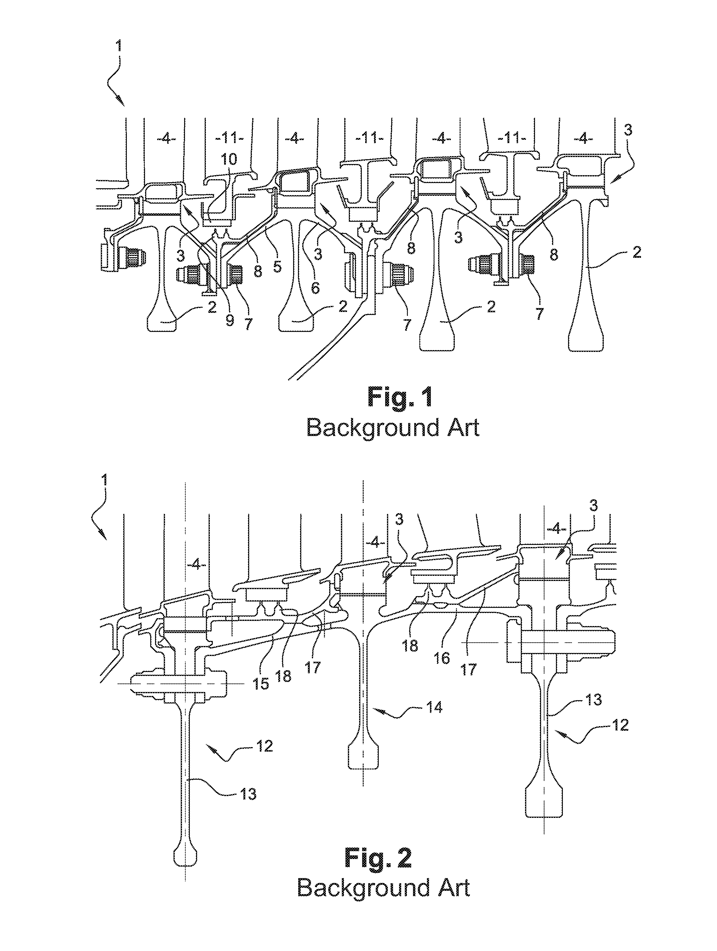
[0028]a prior art turbine rotor 1 is shown in FIG. 1. This rotor 1 comprises a plurality of disks 2 having slots 3 made in their peripheries for mounting blade roots 4. The disks 2 are centered on the axis of the turbine engine and they are connected to one another and to a turbine shaft by upstream and downstream flanges 5, 6, the downstream flange 6 of an upstream disk 2 being fastened to the upstream flange 5 of a downstream disk 2 by means of bolts 7.

[0029]An annular plate 8 for holding the blade roots 4 is fastened by the bolts 7 to the upstream flange 5 of the downstream disk 2 and it extends so as to overlie the slots in the disk and thus form an axial abutment for the blade roots 4 of the disk 2.

[0030]The plate 8 also includes wipers 9 for co-operating with blocks of abradable material 10 mounted on stationary vanes 11 of a set of guide vanes situated axially between the two above-mentioned disks 2, one upstream and the other downstream. The wipers 9 and the abradable blocks...

second embodiment

[0033]a prior art turbine rotor 1 is shown in FIG. 2. This rotor 1 has disks 12, each having a radial rim 13 without any axial flanges. Two disks 12 of this type are then connected together by means of a disk 14 of another type that is interposed axially between them and that has upstream and downstream flanges 15 and 16 of very great length. Ferrules 17 carrying wipers 18 are interposed axially between two disks 12 and are constrained in rotation with the downstream disk 12 by dogs so as to rotate with the rotor 1.

[0034]Although the machining of the disks 12 that do not have flanges can be performed quickly and at low cost, the machining of the intermediate disks 14 remains very considerable since those disks have flanges 15, 16 that are very long.

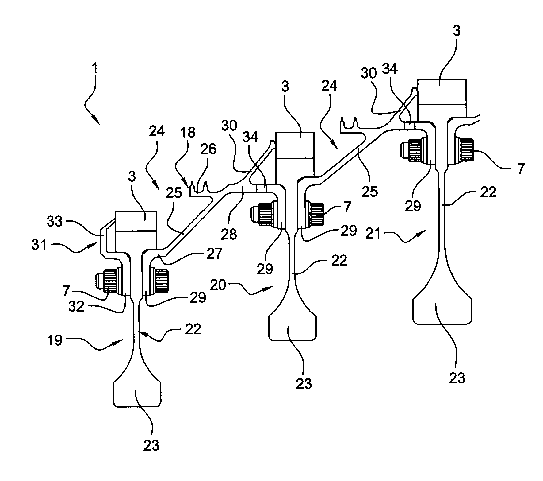
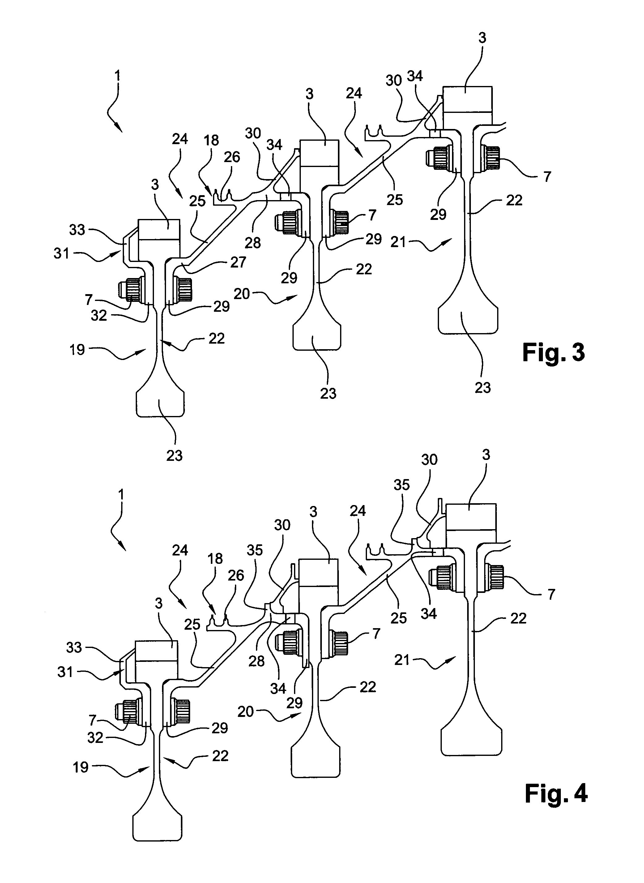
[0035]In order to limit such machining, the invention proposes a set of rotor disks 1, in particular for a low pressure turbine of a turbine engine, with a first embodiment thereof being shown in FIG. 3. This set comprises rotor disks 19,...


PUM


Abstract

A set of rotor disks for a turbine engine, or an airplane turboprop or turbojet, the set including disks rigidly connected together by bolts and shaped at their outer peripheries with slots for mounting blade roots. Each disk includes a rim extending radially and not having any axial flanges, two consecutive disks being connected together with help of an axially-extending ferrule that is fastened to the rims of the disks and that is fitted with a holder plate for holding the blade roots of the downstream disk.

Description

BACKGROUND OF THE INVENTION[0001]1. Field of the Invention[0002]The present invention relates to a set of rotor disks for a turbine engine such as an airplane turboprop or turbojet.[0003]2. Description of the Related Art[0004]In a conventional turbine engine, as described in document EP 2 009 235 in the name of the Applicant, the rotor of the turbine comprises a plurality of disks with slots formed in their peripheries for receiving blade roots. The disks are centered on the axis of the engine and they are connected together and to a turbine shaft by upstream and downstream flanges, the downstream flange of an upstream disk being fastened to the upstream flange of a downstream disk by means of bolts.[0005]An annular holder plate for holding blade roots is fastened to the upstream flange of the downstream disk and extends over the slots of the disk so as to form an axial abutment for the blade roots mounted in the disk.[0006]This plate also carries wipers for co-operating with blocks...

Claims


Application Information

Patent Timeline
Patent Type & Authority Patents(United States)
IPC IPC(8): F01D25/12F01D5/06F01D11/00F01D5/08
CPCF01D5/066F01D5/081F01D11/005F01D25/12Y02T50/676Y02T50/60F01D5/06
Inventor BELMONTE, OLIVIERGALLEGO, LUDOVICWELLER, LIONEL RENE HENRI
Owner SN DETUDE & DE CONSTR DE MOTEURS DAVIATION S N E C M A
Why Eureka
Try Eureka