

Receptacle structure
a technology of receptacle and receptacle, which is applied in the direction of coupling device connection, coupling protective earth/shielding arrangement, two-part coupling device, etc., can solve the problems of reducing the function and meaning of newly released high-speed usb plug and receptacle, affecting signal transmission stability, and affecting the stability of signal transmission, so as to improve shielding protection, stabilize the impedance variation, and improve the effect of high frequency
- Summary
- Abstract
- Description
- Claims
- Application Information
AI Technical Summary
Benefits of technology
Problems solved by technology
Method used
Image

Examples
Embodiment Construction
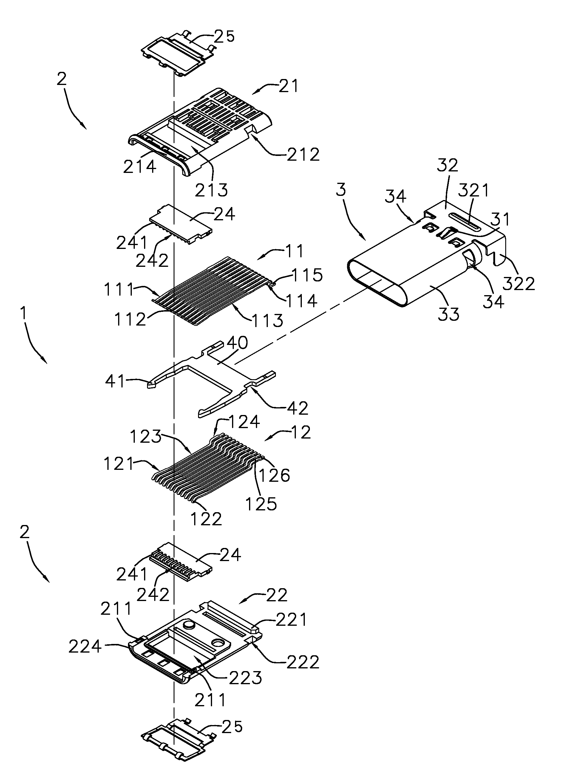
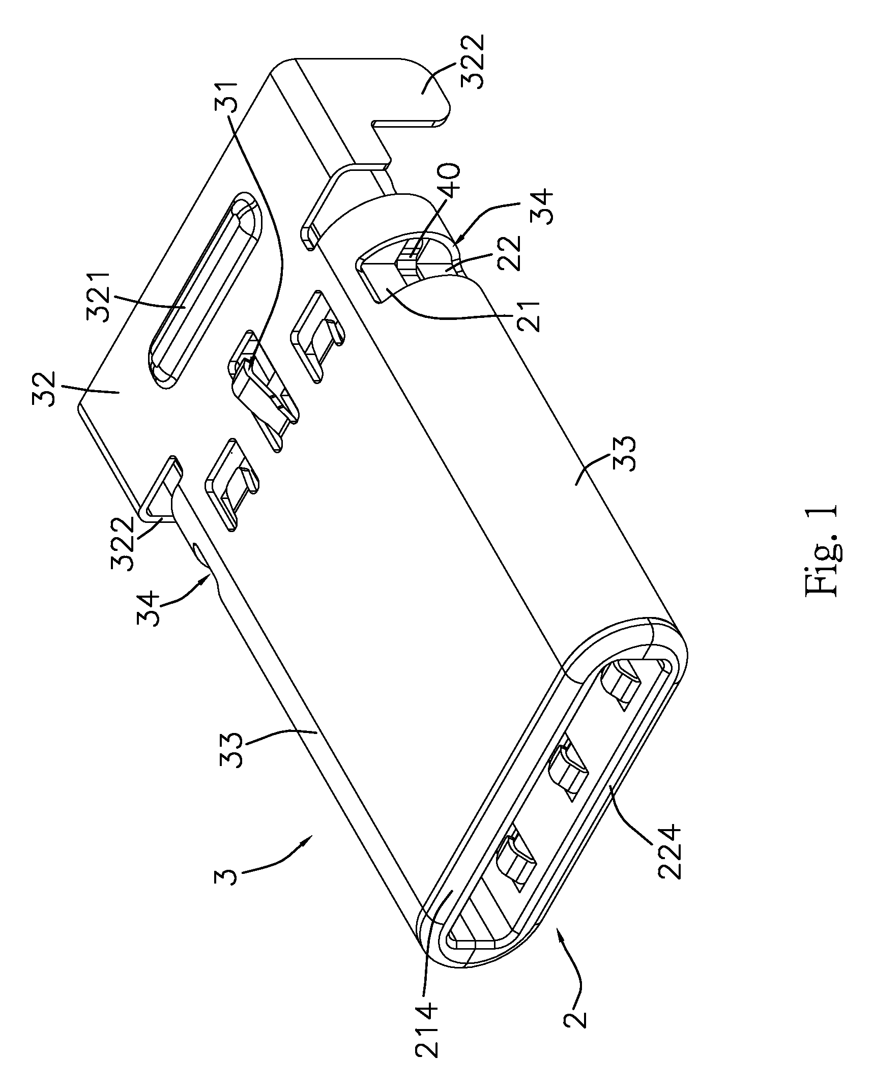
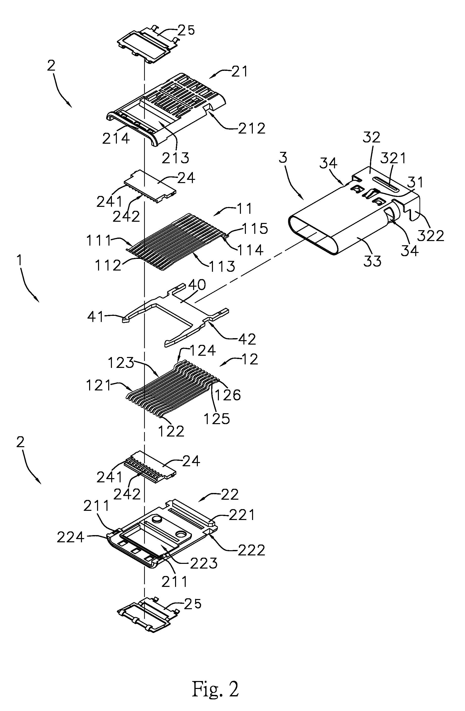
[0025]Please refer to FIG. 1 to FIG. 10 which respectively illustrates those schematic views referring to a receptacle structure and is specifically applied in a structure of USB 3.1 type C. And, it is able to be applied in a SMT or DIP manufacturing process.
[0026]The present invention primarily comprises a joint assembly of terminal 1 with plural signal pins, a main isolator 2 and a metallic casing 3, wherein the terminal 1 with plural pins, configured inside the main isolator 2, is further separated with a upper row terminator 11 and a lower row terminator 12 which respectively contains twelve (12) signal pins (as shown in FIG. 3); the plural signal pins of upper row terminator 11 are bent upward at the fore-part 111 to form as a contact part 112, extends backward a section of mid-part 113, and then are bent downward at the after-part 114 and extended backward as a soldering end 115. Meanwhile, both pin width of fore-part 111 and after-part 114 in the upper row terminator 11 are w...
PUM
 Abstract
Description
Claims
Application Information