Method and apparatus for grid impedance detection

a technology of impedance detection and grid, applied in the direction of resistance/reactance/impedence, impedence measurement, instruments, etc., can solve problems such as hazard for utility line workers or the general public, damage to customer equipment, and potential danger known as “islanding”

Active Publication Date: 2012-12-06
ENPHASE ENERGY
View PDF12 Cites 39 Cited by
  • Summary
  • Abstract
  • Description
  • Claims
  • Application Information

AI Technical Summary

Problems solved by technology

Under some conditions, a grid-connected DG system may become disconnected from the utility grid, resulting in a potentially dangerous condition known as “islanding”.
During islanding, the utility cannot control voltage and frequency in the DG system island, creating the possibility of damage to customer equipment coupled to the island.
Additionally, an island may create a hazard for utility line workers or the general public by causing a line to remain energized while it is assumed that the line has been disconnected from all energy sources.

Method used


Image

  • Method and apparatus for grid impedance detection
  • Method and apparatus for grid impedance detection
  • Method and apparatus for grid impedance detection

Examples


Embodiment Construction

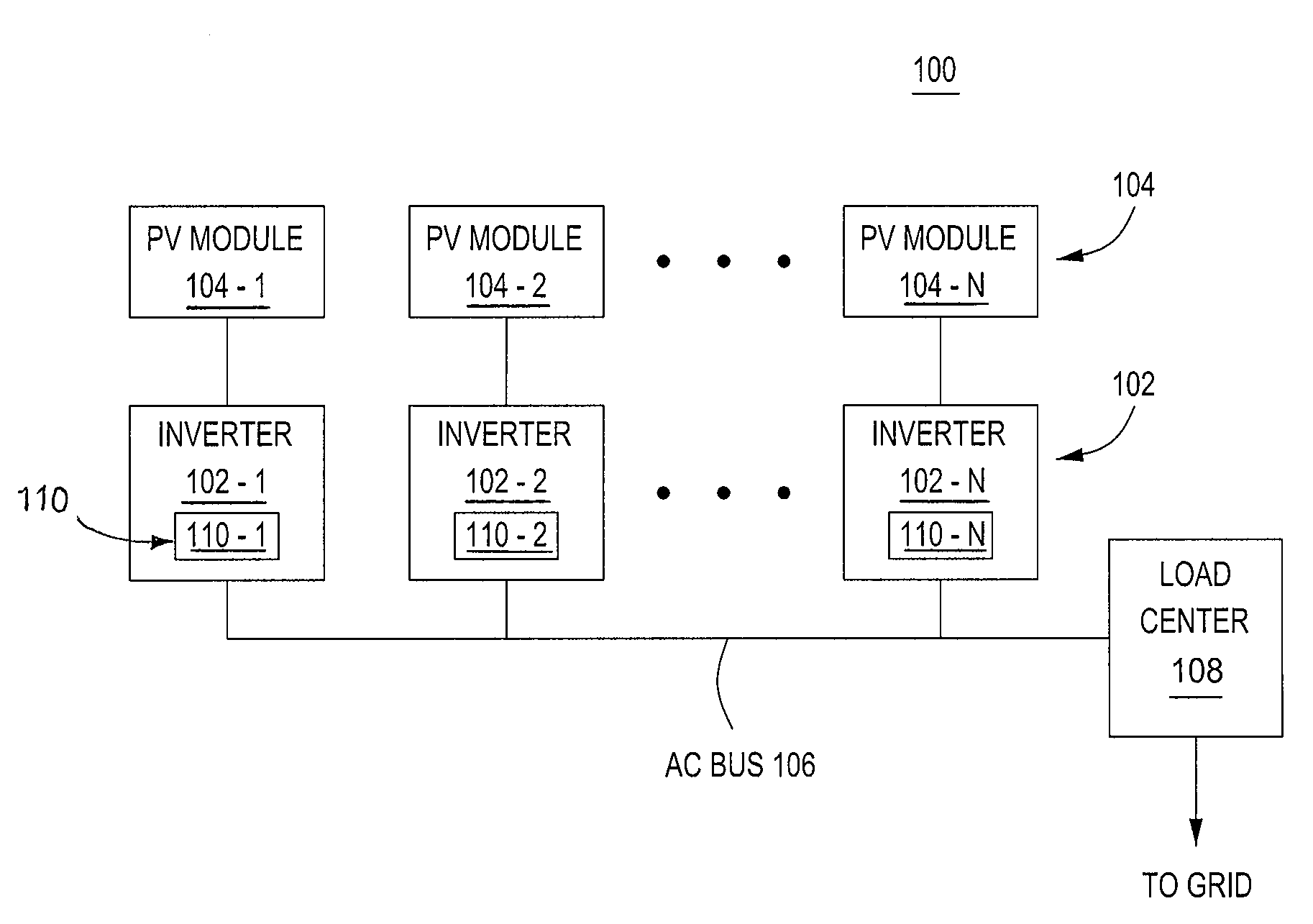
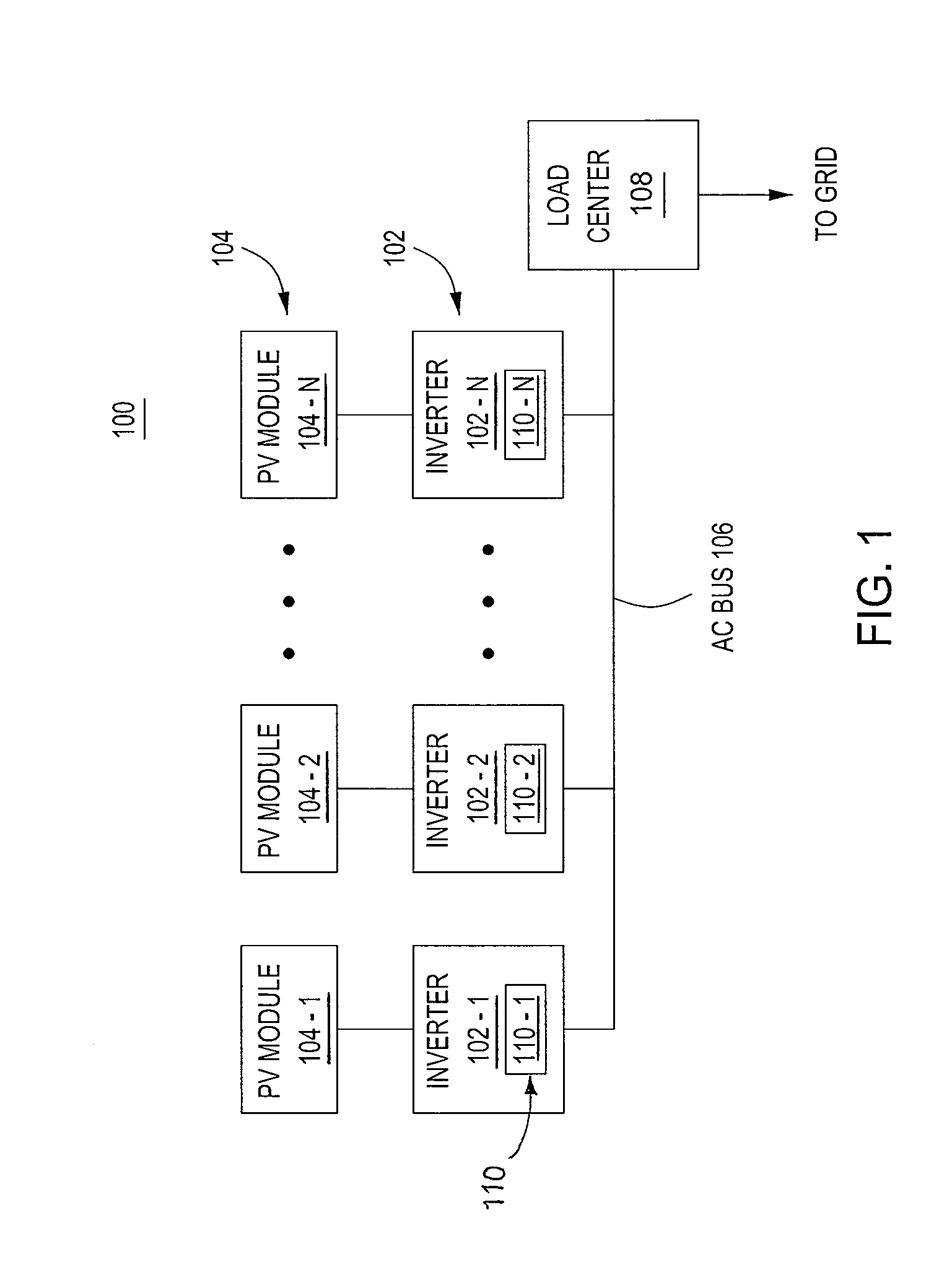
[0016]FIG. 1 is a block diagram of a system 100 for distributed generation (DG) in accordance with one or more embodiments of the present invention. This diagram only portrays one variation of the myriad of possible system configurations. The present invention can function in a variety of distributed power generation environments and systems.

[0017]The system 100 comprises a plurality of inverters (i.e., power converters) 102-1, 102-2 . . . 102-N, collectively referred to as inverters 102, a plurality of PV modules 104-1, 104-2 . . . 104-N, collectively referred to as PV modules 104, an AC bus 106, and a load center 108.

[0018]Each inverter 102-1, 102-2 . . . 102-N is coupled to a PV module 104-1, 104-2 . . . 104-N, respectively, in a one-to-one correspondence. The inverters 102 are further coupled to the AC bus 106, which in turn is coupled to the load center 108. The load center 108 houses connections between incoming power lines from an AC commercial power grid distribution system ...


PUM


Abstract

A method and apparatus for monitoring an AC line for impedance change. In one embodiment, the method, comprises superimposing a tone on an AC current coupled to the AC line, wherein the tone is a higher frequency than an AC voltage waveform on the AC line; applying a correlation over a sampled AC voltage waveform, obtained by sampling the AC voltage waveform, to generate a correlated signal; and determining whether at least one change in characteristic of the correlated signal occurs.

Description

CROSS-REFERENCE TO RELATED APPLICATIONS[0001]This application claims benefit of U.S. provisional patent application Ser. No. 61 / 519,915, filed Jun. 1, 2011, which is herein incorporated in its entirety by reference.BACKGROUND OF THE INVENTION[0002]1. Field of the Invention[0003]Embodiments of the present disclosure relate generally to anti-islanding of distributed power generation systems, and, in particular, to detecting a grid impedance change for anti-islanding.[0004]2. Description of the Related Art[0005]Solar panels, or photovoltaic (PV) modules, convert energy from sunlight received into direct current (DC). The PV modules cannot store the electrical energy they produce, so the energy must either be dispersed to an energy storage system, such as a battery or pumped hydroelectricity storage, or dispersed by a load. One option to use the energy produced is to employ inverters to convert the DC current into an alternating current (AC) and couple the AC current to the commercial A...

Claims


Application Information

Patent Timeline
Patent Type & Authority Applications(United States)
IPC IPC(8): G01R27/16
CPCH02J3/383G01R27/16Y02E10/563H02J2003/388H02J3/388H02J2300/24H02J3/381Y02E10/56
Inventor BARNES, ANDREWACKER, BRIAN
Owner ENPHASE ENERGY
Why Eureka
Try Eureka