
Power grid impedance measurement method and device

A technology of power grid impedance and measurement method, applied in the direction of impedance measurement, etc., can solve the problem of small distortion degree of three-phase alternating current current or voltage, and achieve the effect of reducing the degree of distortion

Active Publication Date: 2016-11-23
EMERSON NETWORK POWER CO LTD
View PDF8 Cites 8 Cited by
  • Summary
  • Abstract
  • Description
  • Claims
  • Application Information

AI Technical Summary

Problems solved by technology

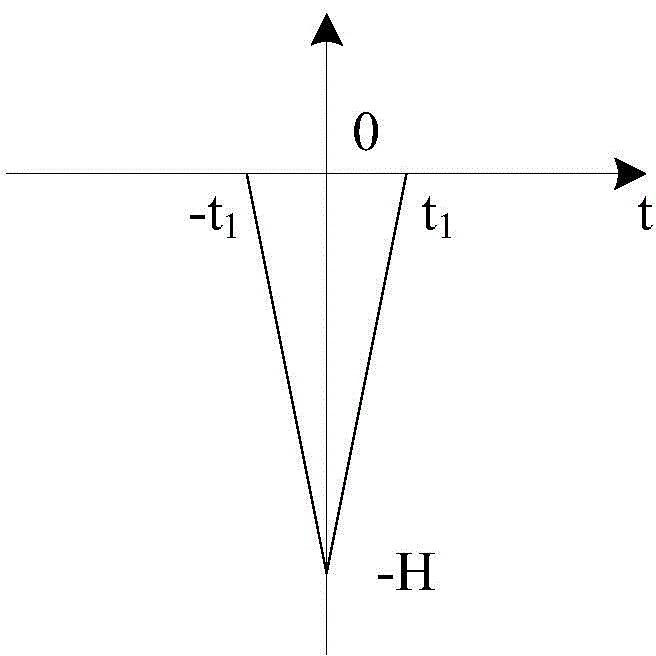
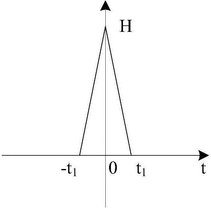
[0009] To sum up, at present, when the active injection method is used to measure the grid impedance, it is generally believed that at the peak moment of a certain phase current, injecting a unipolar pulse into the current reference of the d-axis to measure the grid impedance will make the three-phase AC The phase with the largest current or voltage distortion will be the least distorted

Method used


Image

  • Power grid impedance measurement method and device
  • Power grid impedance measurement method and device
  • Power grid impedance measurement method and device

Examples


Embodiment Construction

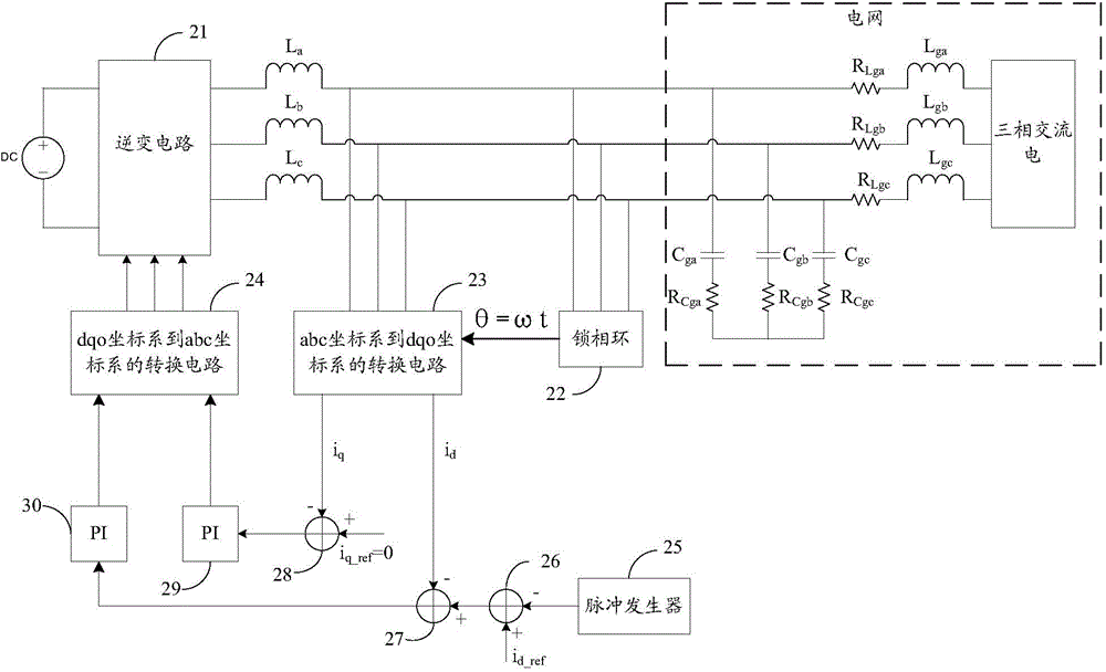
[0032] The embodiment of the present invention provides a method and device for measuring grid impedance, by applying a pulse signal to the grid at the given d-axis current at the first moment, the first moment being the current of any phase except the three-phase alternating current It is a moment other than the peak moment, so as to determine the impedance of the grid at different frequencies, so that the impedance of the grid can be measured, and the largest distortion of current or voltage in the three-phase alternating current caused by the injected pulse can be reduced. phase distortion.

[0033] The specific implementation manners of a grid impedance measurement method and device provided in the embodiments of the present invention will be described below with reference to the drawings in the description.

[0034] figure 2 The principle block diagram for measuring grid impedance provided by the embodiment of the present invention: the inverter circuit 21 converts the ...


PUM


Abstract

The invention provides a power grid impedance measurement method and a device and solves a problem that one phase of a three-phase AC current supposed to have the largest current or voltage deformation degree has the smallest current or voltage deformation degree because of injected pulses when the single-polarity pulses are injected to a current given of a d axis at the peak time of a certain phase current in the prior art employing an active injection mode to measure power grid impedance. The method comprises steps that a pulse signal is applied to a power grid on the current given of the d axis at the first time, and the first time is the time when a current of any phase of the three-phase AC current is not a peak value; the voltage and the current of the power grid during pulse signal applying are determined; the power grid impedance is determined according to the determined voltage and the determined current of the power grid.

Description

technical field [0001] The invention relates to the technical field of power electronics, in particular to a method and device for measuring grid impedance. Background technique [0002] Power electronics technology is increasingly penetrated into the field of electric energy production and processing, and its impact cannot be ignored. The interaction of power electronic converters with power systems introduces new risks, among them stability issues. [0003] The power electronic converter with constant power load characteristics has negative impedance characteristics at its input, which may lead to system instability. Large power grids can withstand these negative impedance characteristics, but many small power systems cannot, such as spacecraft, ships, hybrid vehicles, and microgrid systems. These small systems will become increasingly common in both industrial and civilian applications, making it imperative that we be able to predict and test them to ensure their safe o...

Claims


Application Information

Patent Timeline
IPC IPC(8): G01R27/16
Inventor 刘进军包维翰刘方诚刘增崔志洋
Owner EMERSON NETWORK POWER CO LTD
Learn More