Modular electrical raceway for buildings

a technology of electrical raceways and modules, applied in the direction of coupling device connections, walls, schools, etc., can solve the problems of inability to install electrical, plumbing, duct rough-ins, current construction methods, etc., and achieve the effect of reducing time and cost of wiring and improving maintenance eas

Active Publication Date: 2016-06-21
TANNENBAUM JEROME S
View PDF26 Cites 23 Cited by
  • Summary
  • Abstract
  • Description
  • Claims
  • Application Information

AI Technical Summary

Benefits of technology

[0017]An object of the present disclosure is to reduce the time and cost of wiring the circuit branches of a hospital or healthcare facility during new construction and / or renovation.
[0018]Another object of the present disclosure is to assure the proper identification of each circuit from the electrical distribution panel to the outlet or junction box device, and every step in between, for improved ease of maintenance compared with conventional methods of labeling and circuit testing.

Problems solved by technology

Furthermore, the current method of construction is very sequential in that each skilled trade must be sequenced to perform their work at various time points during the construction process.
For example, in the traditional approach to construction the electrical, plumbing, and duct rough-in cannot be installed until the stud walls and roof deck are installed.
In many applications, considerable time and expense could be saved if such rooms or parts of rooms could be pre-assembled off-site as pre-fabricated sub-assemblies and installed and connected to each other at the construction location.
However, considerable time and expense could also be saved if such components could be pre-assembled offsite as pre-fabricated sub-assemblies and joined with other components at the construction location.
Hospitals and healthcare facilities have complex power distribution requirements.
The cost of installing these branch circuits is significant and time consuming.
Conduit and junction boxes are frequently labeled with a color code as to the type of power (e.g. critical branch, normal, etc.) but are often not labeled with the specific panel and circuit number, making it difficult to trace a fault in a particular circuit.

Method used


Image

  • Modular electrical raceway for buildings
  • Modular electrical raceway for buildings
  • Modular electrical raceway for buildings

Examples


Embodiment Construction

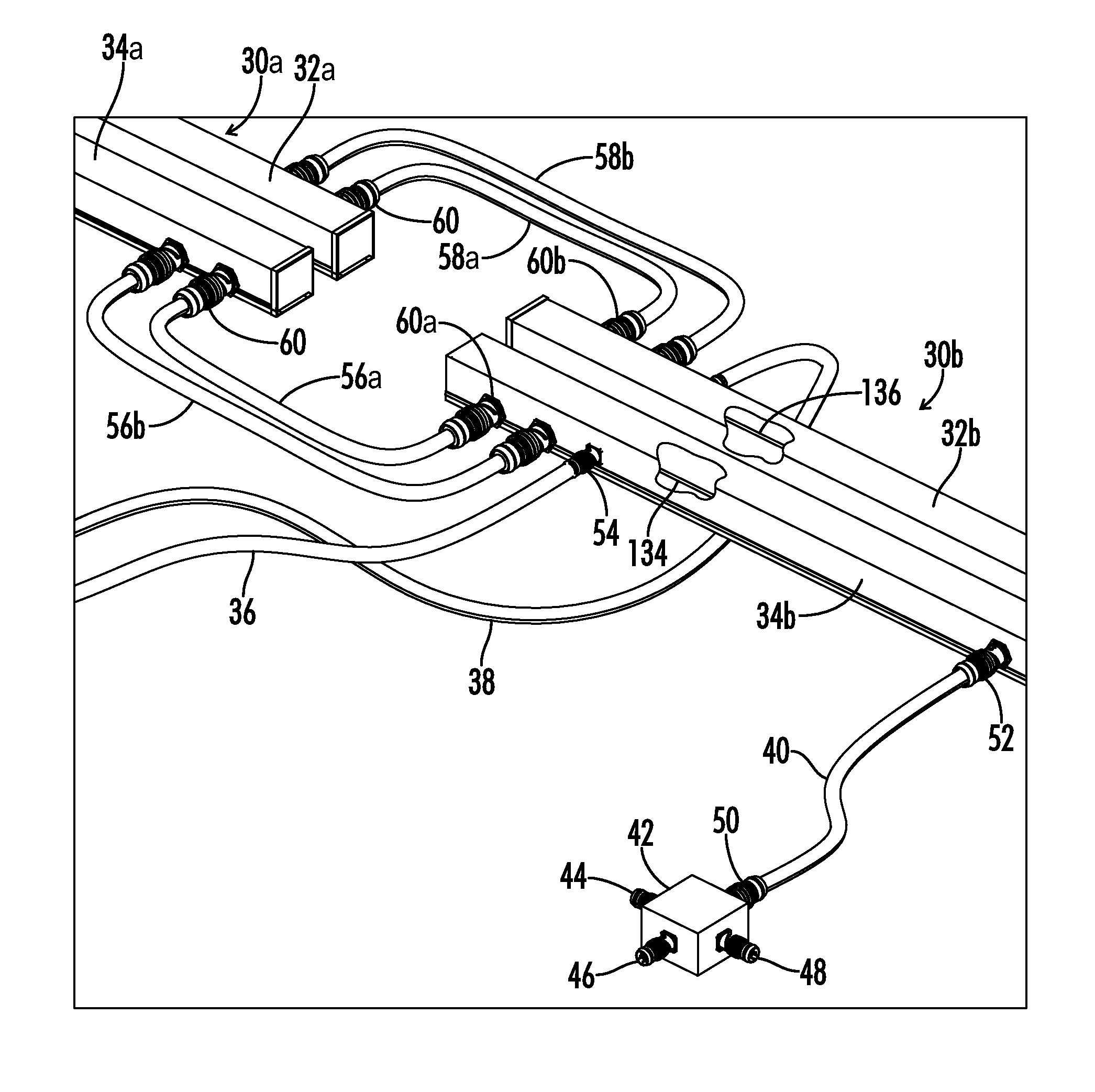
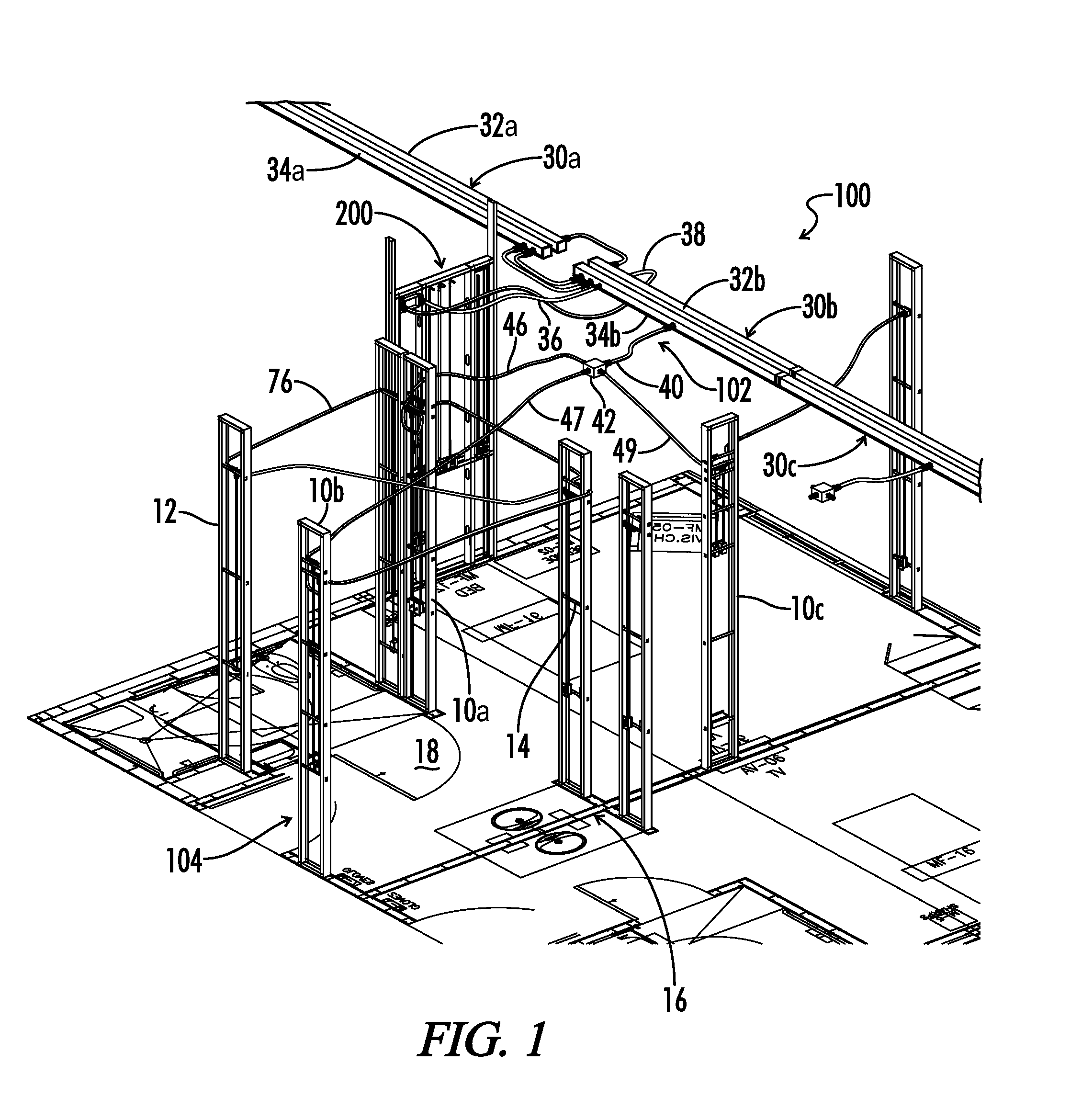
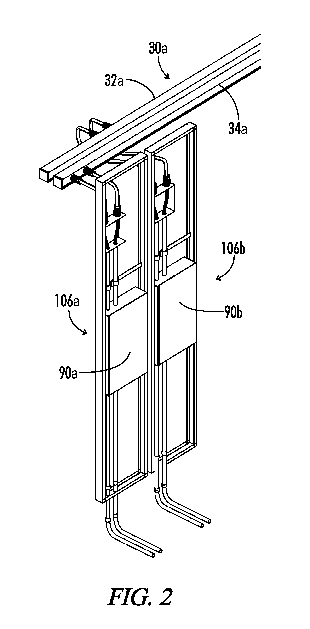
[0085]Referring now to the drawings, FIG. 1 illustrates an exemplary embodiment of a modular building system 100 in accordance with the present disclosure. Building system 100 includes a plurality of modular wall panel units 10a, 10b, 10c that may be prefabricated and prewired prior to installation at a construction location. Each wall panel unit 10 includes electrical, plumbing and / or communication hardware pre-installed such that the panel may be shipped to a construction location and subsequently connected to a corresponding electrical, plumbing or communication system. Each modular wall panel unit 10 includes a metal frame in some embodiments and can be positioned at a location on a floor plan 16 at a desired use location for the hardware features installed thereon.

[0086]Multiple branch circuit connectors 40 are attached to each local raceway unit for providing a branch circuit to individual rooms or groups of rooms in the building. Each branch circuit may include a plurality of...


PUM


Abstract

A modular raceway apparatus provides a pre-wired electrical sub-assembly for on-site installation in a building or installation a pre-fabricated building component. The raceway apparatus includes normal power and emergency power tracks. Each power track includes internal wiring connected to one or more connectors for plug-and-play interconnectivity with independent power supplies and other electrical component wiring members. Each raceway track includes multiple track members separated by gaps and a coupling.

Description

CROSS-REFERENCES TO RELATED APPLICATIONS[0001]This nonprovisional utility patent application claims benefit of and priority to U.S. provisional patent application No. 61 / 669,499 filed Jul. 9, 2012 entitled Pre-Fabricated Multi-Trade Sub-Assembly System and Methods, all of which is hereby incorporated by reference in its entirety.[0002]A portion of the disclosure of this patent document contains material that is subject to copyright protection. The copyright owner has no objection to the reproduction of the patent document or the patent disclosure, as it appears in the U.S. Patent and Trademark Office patent file or records, but otherwise reserves all copyright rights whatsoever.STATEMENT REGARDING FEDERALLY SPONSORED RESEARCH OR DEVELOPMENT[0003]Not ApplicableREFERENCE TO SEQUENCE LISTING OR COMPUTER PROGRAM LISTING APPENDIX[0004]Not ApplicableBACKGROUND[0005]1. Technical Field[0006]The present invention relates generally to devices and methods for constructing buildings and more pa...

Claims


Application Information

Patent Timeline
Patent Type & Authority Patents(United States)
IPC IPC(8): H02G3/04
CPCH02G3/0437H02G3/00A61G12/002A61G12/005E04B2002/7488E04F17/08E04H3/08H01R13/73H01R31/06H02G3/06H02G3/128H02G3/30
Inventor TANNENBAUM, JEROME S
Owner TANNENBAUM JEROME S
Why Eureka
Try Eureka