Post fabrication tuning of an integrated circuit

a technology of integrated circuits and tuning techniques, applied in the direction of single output arrangements, pulse manipulation, electrical equipment, etc., can solve the problems of relatively coarse grain in tuning techniques, not applicable in all directions, etc., to improve the reliability and potential speed of operation, improve the matching speed of the pair of transistors, and improve the performance

Active Publication Date: 2016-06-21
ARM LTD
View PDF7 Cites 6 Cited by
  • Summary
  • Abstract
  • Description
  • Claims
  • Application Information

AI Technical Summary

Benefits of technology

[0015]Depending upon the mechanism by which the physical properties of the transistor are changed, the tuning electrical signal could be applied at different ones of the connections to the transistor. In some embodiments, the tuning electrical signal is applied to the gate connection of the transistor. Applying a voltage to the gate of a transistor which is outside of the normal range can have the effect of changing the threshold voltage of the transistor such that the switching speed of the transistor is decreased.
[0016]In other embodiments the tuning electrical signal may be applied to the drain connection of a transistor. In some circumstances applying a tuning electrical signal with a voltage outside of the normal range of voltages to the drain connection can have the effect of increasing the switching speed of the transistor.
[0021]One way in Which the present technique may be used is when the integrated circuit includes a pair of transistors having at least partially matched switching speeds. The tuning electrical signal may be applied to a first of this pair so as to change its switching speed to more closely match the switching speed of a second of the pair. Better matching of the switching speeds of the pair of transistors may produce improved performance. An example of such a situation is when the pair of transistors are part of a sense amplifier within an integrated circuit memory. Balancing of the speed of operation of different transistors within a sense amplifier improves the reliability and potential speed of operation of the sense amplifier.
[0022]Another way in which the present techniques may be used to improve the performance of a sense amplifier within a memory is when the transistor is part of a current source. Such a current source will typically control the slew rate of the sense amplifier and changing the speed of operation of the transistor will in turn change the slew rate. Changing the slew rate to match a desired slew rate can improve the reliability and speed of operation of the memory.
[0024]Another example use of the present technique is within an integrated circuit that includes a transistor stack which is configured to generate an output signal which is either pulled up to a first voltage level or pulled down to a second voltage level in dependence upon an input signal. The transistor may be part of this transistor stack such that changing the switching speed of the transistor changes at least one of the speed at which the output signal is pulled up or pulled down. Adjusting the speed with which the output signal is generated can influence the timing of signals within the integrated circuit in a manner which can improve reliability or otherwise improve the performance of the integrated circuit.

Problems solved by technology

Such tuning techniques are relatively coarse grained and are not applicable to all areas within a circuit where it might be desired to speed up or slow down the speed of operation.

Method used


Image

  • Post fabrication tuning of an integrated circuit
  • Post fabrication tuning of an integrated circuit
  • Post fabrication tuning of an integrated circuit

Examples


Embodiment Construction

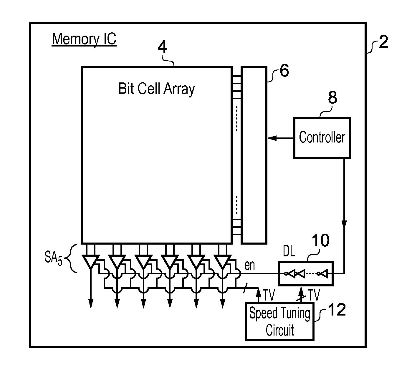
[0049]FIG. 1 schematically illustrates an integrated circuit in the form of a memory 2. The memory includes a bit cell array 4, a row decoder 6 and sense amplifiers SA. A timing controller 8 generates timing signals which control the row decoder and, via a delay line 10, the enable signal (en) supplied to the sense amplifiers SA for reading the bit line pairs. Speed tuning circuitry 12 is coupled to both the delay line 10 and the sense amplifiers SA to apply a tuning voltage to transistors within the delay line 10 or the sense amplifiers SA so as to change their switching speed.

[0050]The normal operation of the memory 2 will use voltages for switching the gates of transistors within the sense amplifiers SA and the delay line 10 that are within a normal range of voltages. If the change in the speed of switching of any of those transistors is desired then the speed tuning circuit 12 during a tuning operation applies a tuning voltage outside of this normal range to the transistors so a...


PUM


Abstract

An integrated circuit 2 includes a transistor 26 which has a normal switching speed arising during normal operations of that transistor that apply electrical signals within normal ranges. If it is desired to change the speed of operation of the transistor, then speed tuning circuitry 12 applies a tuning electrical signal with a tuning characteristic outside of the normal range of characteristics to the transistor concerned. The tuning electrical signal induces a change in at least one of the physical properties of that transistor such that when it resumes its modified normal operations the switching speed of that transistor will have changed. The tuning electrical signal may be a voltage (or current) outside of the normal range of voltages applied to the gate of a transistor so as to induce a permanent increase in the threshold of that transistor and so slow its speed of switching. Temperature of a transistor may also be controlled to induce a permanent change in performance / speed.

Description

[0001]This is a continuation-in-part application of U.S. patent application Ser. No. 13 / 706,718 the content of which is in incorporated herein in its entirety by reference.BACKGROUND OF THE INVENTION[0002]1. Field of the Invention[0003]This invention relates to the field of integrated circuits. More particularly, this invention relates to the tuning of the operation of integrated circuits after their manufacture.[0004]2. Description of the Prior Art[0005]It is known to provide integrated circuits with tuning mechanisms that may be used after manufacture, for example, to adjust the timing of certain control signals. As an example, a control signal may propagate through a delay line and the number of inverters in the signal path of that delay line may be changed so as to control the amount of delay applied to the control signal. Such tuning techniques are relatively coarse grained and are not applicable to all areas within a circuit where it might be desired to speed up or slow down t...

Claims


Application Information

Patent Timeline
Patent Type & Authority Patents(United States)
IPC IPC(8): H03K5/133H03K5/13
CPCH03K5/133
Inventor HOLD, BETINACLINE, BRIANLATTIMORE, GEORGE
Owner ARM LTD
Why Eureka
Try Eureka