
Methods and apparatus relating to a camera including multiple optical chains

a technology of optical chains and cameras, applied in the field of cameras including multiple optical chains, can solve the problems of large bulky and often costly lenses, large telephoto lenses, and heavy lenses, and achieve the effect of facilitating a compact camera design

Active Publication Date: 2016-06-21
BLUE RIVER TECH
View PDF111 Cites 34 Cited by
  • Summary
  • Abstract
  • Description
  • Claims
  • Application Information

AI Technical Summary

Benefits of technology

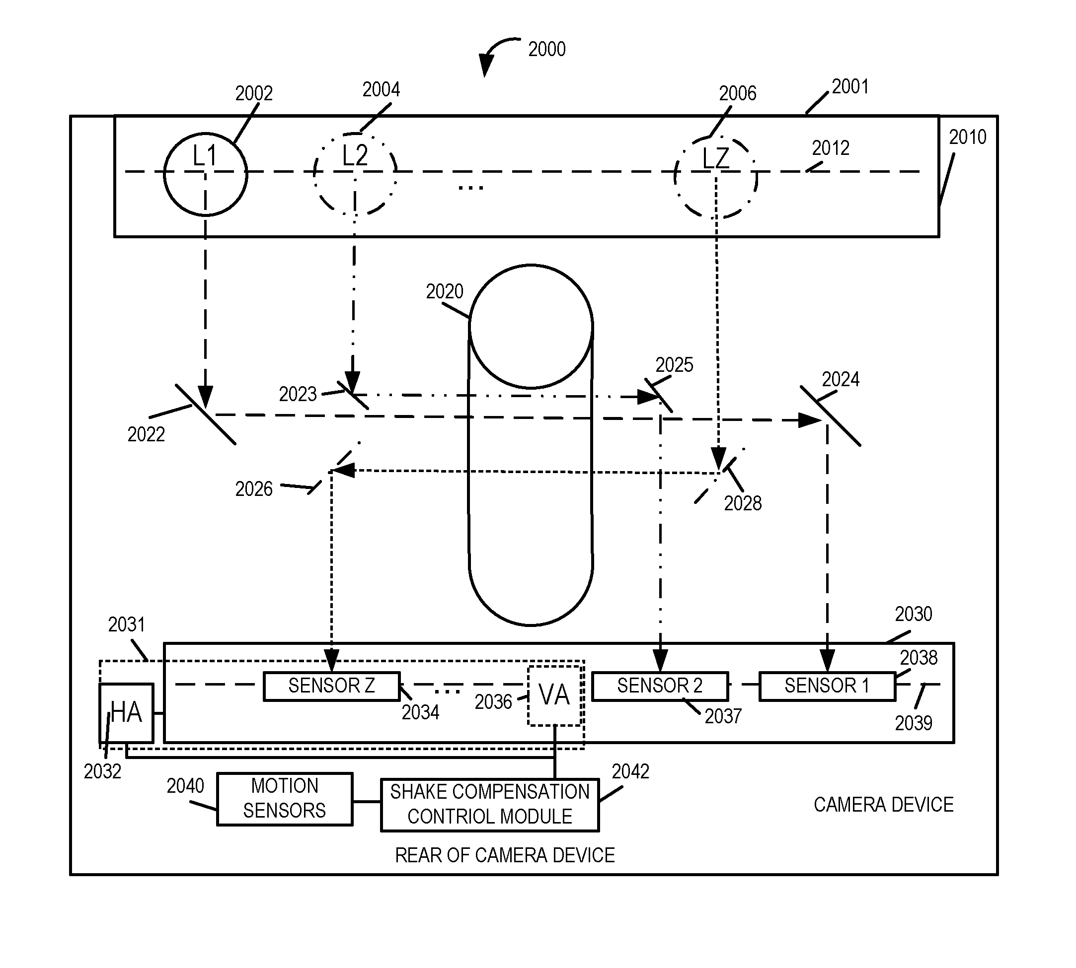
The invention is about a sensor device that uses multiple optical chains to capture images. The sensors are mounted on a flat printed circuit board or backplane that can be attached to actuators that move to compensate for camera shake. The device uses mirrors to direct the light in a way that allows the sensors to capture images perpendicular to the camera. This design allows for longer optical paths and makes use of the camera's width. The use of mirrors or other light diverting devices allows the sensors to be located at the rear or front of the camera. The technical effect is improved image quality and stability during camera movement.

Problems solved by technology

Individuals seeking to take quality photographs are often encouraged to invest in large bulky and often costly lenses for a variety of reasons.
Telephoto lenses tend to be large not only because of their large apertures but also because of their long focal lengths.
While large lenses have many advantages with regard to the ability to capture relatively large amounts of light compared to smaller lenses, support large zoom ranges, and often allow for good control over focus, there are many disadvantages to using large lenses.
Large lenses tend to be heavy requiring relatively strong and often large support structures to keep the various lenses of a camera assembly in alignment.
The heavy weight of large lenses makes cameras with such lenses difficult and bulky to transport.
Furthermore, cameras with large lenses often need a tripod or other support to be used for extended periods of time given that the sheer weight of a camera with a large lens can become tiresome for an individual to hold in a short amount of time.
In addition to weight and size drawbacks, large lenses also have the disadvantage of being costly.
This is because of, among other things, the difficultly in manufacturing large high quality optics and packaging them in a manner in which they will maintain proper alignment over a period of time which may reflect the many years of use a camera lenses is expected to provide.
However, for the vast majority of camera users, the drawbacks to cameras with large lenses means that camera users tend not to use large lenses with such lenses often being left to professionals and / or photo enthusiasts willing to incur the expense and trouble of buying and using large lenses.
For example, cell phone mounted cameras are often more readily available for use when an unexpected photo opportunity arises or in the case of a general family outing where carrying large bulky camera equipment may be uncomfortable or undesirable.
While a filter arrangement over a sensor array can be used to allow different sensor elements to capture different colors of light thus allowing a single sensor to capture a color image, the need to carefully align the filter area with individual pixel size sensor elements complicates the manufacture of sensor arrays as compared to arrays which do not require the use of a multi-color filter array.
While small focal length lenses paired with relatively high resolution sensors have achieved widespread commercial success in cell phones and pocket cameras, they often leave their owners longing for better picture quality, e.g., picture quality that can only be achieved with a larger pixel area and a larger lens opening to collect more light.
However, there are a few disadvantages to using smaller sensors and lenses.
First, the small pixel size limits the dynamic range of the sensor as only a small amount of light can saturate the sensor.
Second, small lenses collect less total light which can result in grainy pictures.
Third, small lenses have small maximum apertures which make artistic effects like small depth of field for portrait pictures not possible.

Method used


Image

  • Methods and apparatus relating to a camera including multiple optical chains
  • Methods and apparatus relating to a camera including multiple optical chains
  • Methods and apparatus relating to a camera including multiple optical chains

Examples


Embodiment Construction

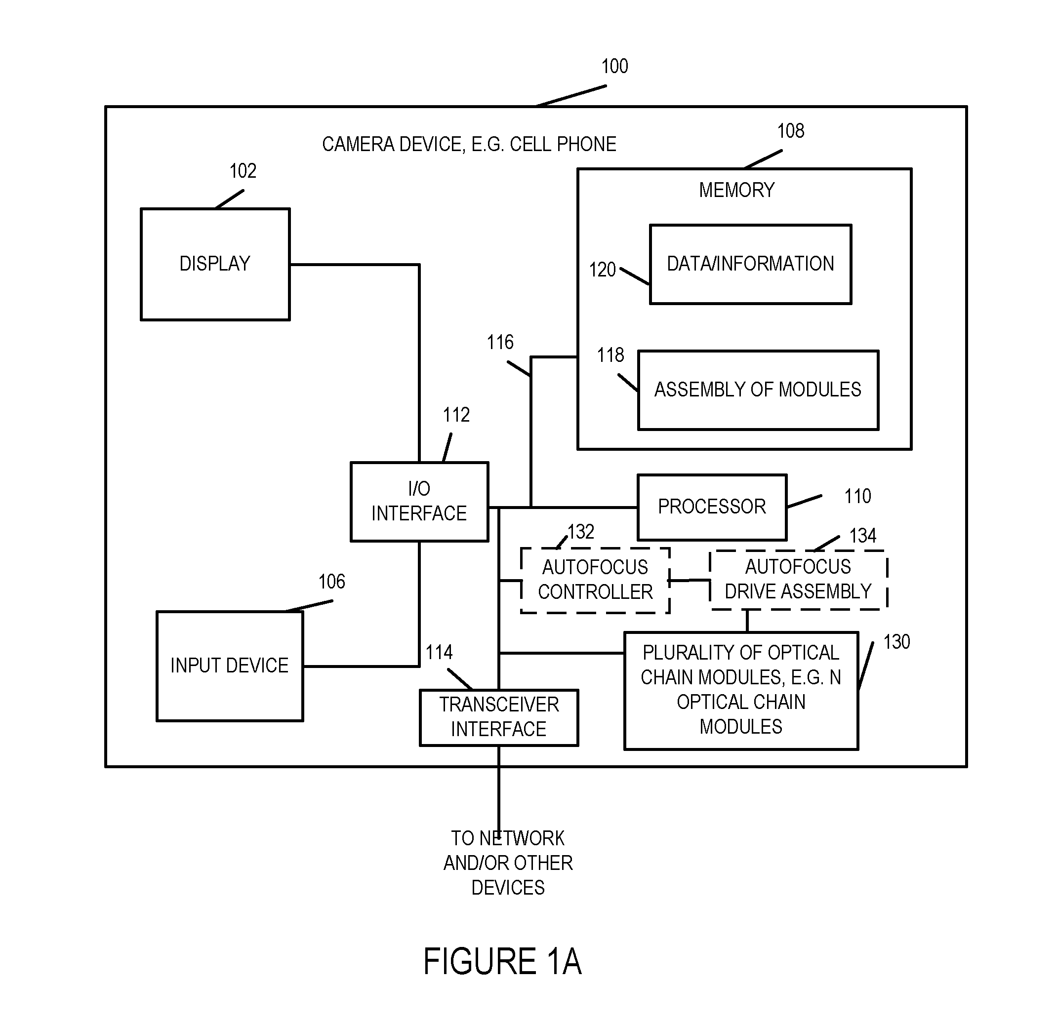
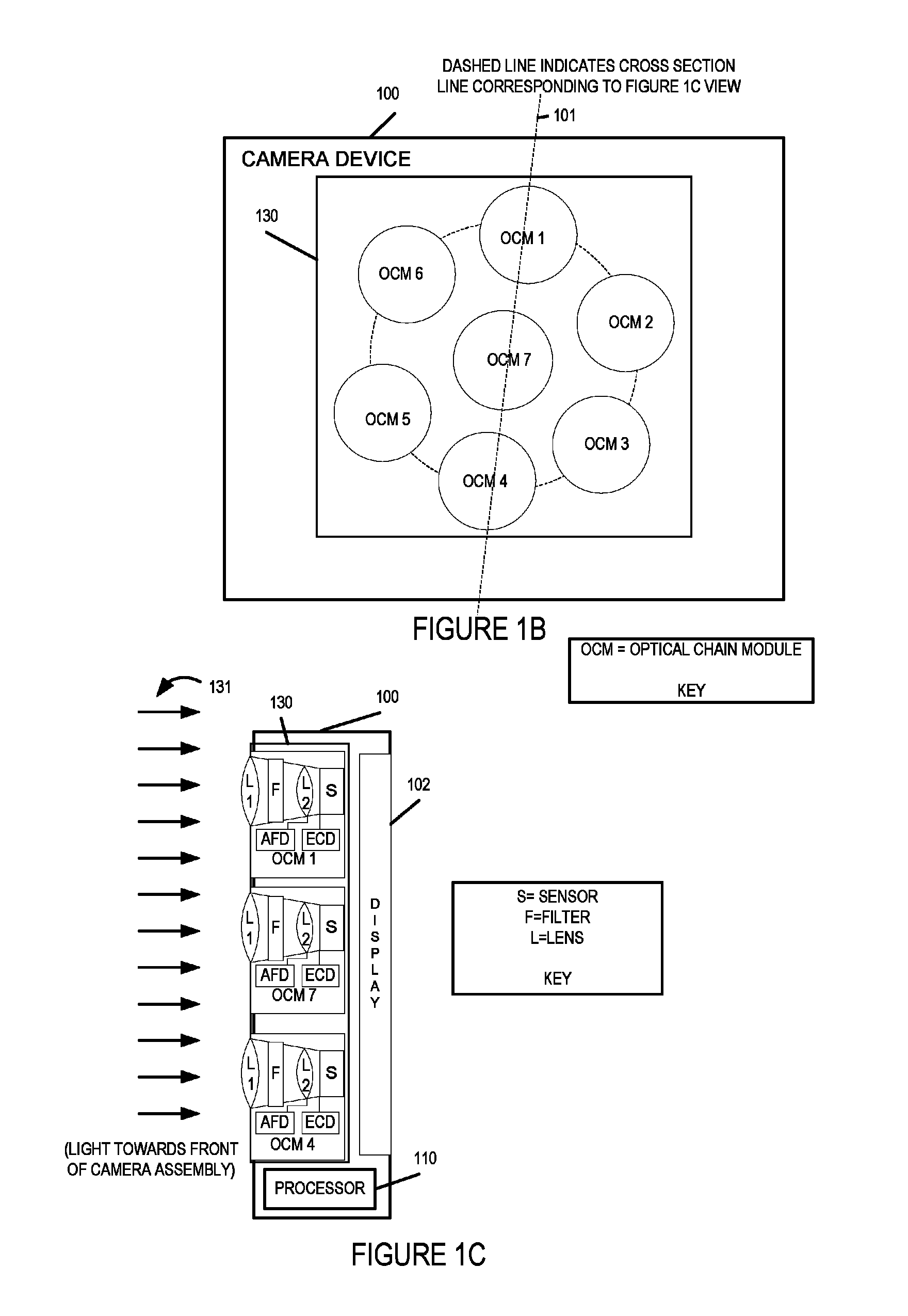
[0056]FIG. 1A illustrates an exemplary apparatus 100, sometimes referred to hereinafter as a camera device, implemented in accordance with one exemplary embodiment of the present invention. The camera device 100, in some embodiments, is a portable device, e.g., a cell phone or tablet including a camera assembly. In other embodiments, it is fixed device such as a wall mounted camera.

[0057]FIG. 1A illustrates the camera device 100 in block diagram form showing the connections between various elements of the apparatus 100. The exemplary camera device 100 includes a display device 102, an input device 106, memory 108, a processor 110, a transceiver interface 114, e.g., a cellular interface, a WIFI interface, or a USB interface, an I / O interface 112, and a bus 116 which are mounted in a housing represented by the rectangular box touched by the line leading to reference number 100. The input device 106 may be, and in some embodiments is, e.g., keypad, touch screen, or similar device that ...


PUM


Abstract

Camera methods and apparatus are described where the camera device includes multiple optical chains. In various embodiments two or more of the optical chains include light redirection devices such as mirrors or prisms. Sensors corresponding to multiple different optical chains, but not necessarily all optical chains, are parallel to each other. In some embodiments sensors corresponding to different optical chains are located in the same plane at the front or rear of the camera. However other sensor mounting positions are also possible.

Description

RELATED APPLICATIONS[0001]The present application claims the benefit of the following U.S. Provisional Patent Applications 61 / 978,818 filed Apr. 11, 2014; 61 / 981,849 filed Apr. 20, 2014; 62 / 021,094 filed Jul. 4, 2014; 61 / 893,100 filed Oct. 18, 2013; 61 / 896,069 filed Oct. 26, 2013; 61 / 899,097 filed Nov. 1, 2013; 61 / 922,801 filed Dec. 31, 2013; 61 / 943,299 filed Feb. 21, 2014; and 61 / 943,302 filed Feb. 21, 2014; and is a continuation-in-part of each of the following U.S. patent applications: Ser. No. 14 / 327,510 filed Jul. 9, 2014; Ser. No. 14 / 327,512 filed Jul. 9, 2014; Ser. No. 14 / 327,514 filed Jul. 9, 2014; Ser. No. 14 / 327,515 filed Jul. 9, 2014; Ser. No. 14 / 327,517 filed Jul. 9, 2014; Ser. No. 14 / 327,518 filed Jul. 9, 2014; Ser. No. 14 / 327,492 filed Jul. 9, 2014; Ser. No. 14 / 327,524 filed Jul. 9, 2014; Ser. No. 14 / 327,525 filed Jul. 9, 2014; and Ser. No. 14 / 327,508 filed Jul. 9, 2014, and all of the aforementioned patent applications are hereby incorporated by reference in their ent...

Claims


Application Information

Patent Timeline
Patent Type & Authority Patents(United States)
IPC IPC(8): H04N5/225H04N5/28G02B17/08G02B17/00G02B13/00H04N5/232
CPCG02B13/0065G02B17/008G02B17/08H04N5/2254H04N5/28H04N5/2258H04N5/23212H04N5/23232H04N5/23258H04N5/23287H04N23/45H04N23/55H04N23/67H04N23/951H04N23/6812H04N23/687H04N23/843H04N25/134G02B5/04
Inventor LAROIA, RAJIV
Owner BLUE RIVER TECH
Learn More