Hinge for pieces of furniture with a frame

a technology for furniture and hinges, applied in the direction of door/window fittings, multi-purpose tools, construction, etc., can solve the problems of inconvenient adjustment, lend a certain degree of complexity to the assembly operations of various parts, and the hinge arm is more compact, so as to achieve reliable and accurate adjustment of the hinge arm and high coupling resistance

Active Publication Date: 2016-06-28
ARTURO SALICE
View PDF12 Cites 3 Cited by
  • Summary
  • Abstract
  • Description
  • Claims
  • Application Information

AI Technical Summary

Benefits of technology

[0020]In a further embodiment the adjusting screw for the adjustment in a perpendicular direction to the longitudinal rest plane of the base plate is screwed into a threaded hole of the hinge arm and is rotatably retained therein with a lower shank thereof, but is not axially displaceable in a circular hole in the base plate, below which the shank of the screw is riveted. This solution guarantees a reliable and accurate adjustment of the hinge arm together with a high resistance of the coupling between the parts.

Problems solved by technology

In known hinges, for example U.S. Pat. No. 6,647,591 and U.S. Pat. No. 6,845,544, the base and intermediate plates and the hinge arm are also connected to one another by means of a transversal pin, so that the arrangement of the various connecting and adjusting means between the parts prevents the hinge from being more compact and also lends a certain degree of complexity to the assembly operations of the various parts.
Further, in these known constructional embodiments, the adjusting screw engages with its thread on the edges or profiled wings at an opening of the hinge arm; this is a solution that can lead to imprecision in adjustment and problems of resistance in the coupling between the parts.

Method used


Image

  • Hinge for pieces of furniture with a frame
  • Hinge for pieces of furniture with a frame
  • Hinge for pieces of furniture with a frame

Examples


Embodiment Construction

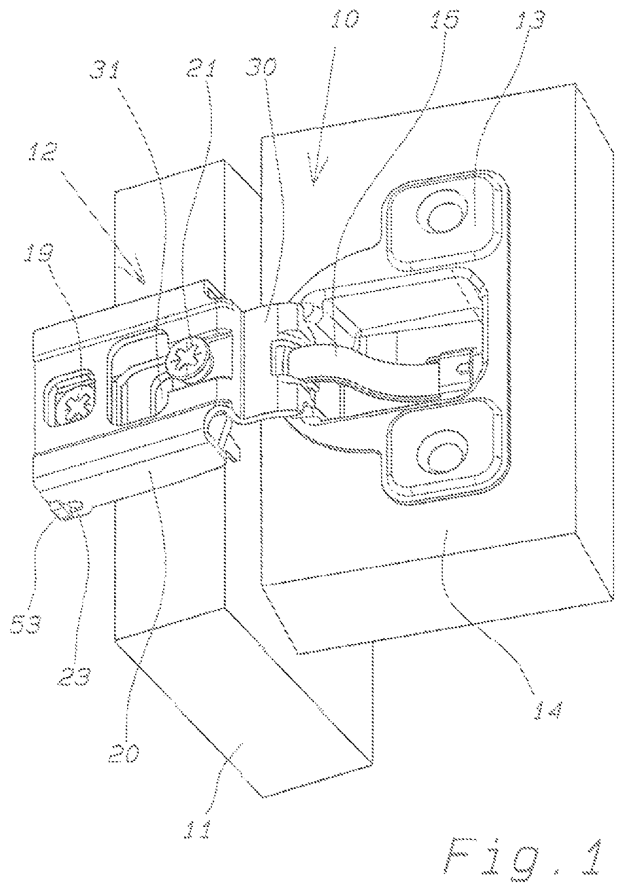
[0025]The hinge of the present invention, denoted in its entirety in the accompanying figures by reference numeral 10, is applicable to pieces of furniture of the American type provided with a front frame 11 on which the hinges are fixed. This type of hinge 10 in general comprises a fixed part 12 for fixing the hinge itself to the front frame 11 of the piece of furniture and a box 13 for fixing to a door 14 of the piece of furniture.

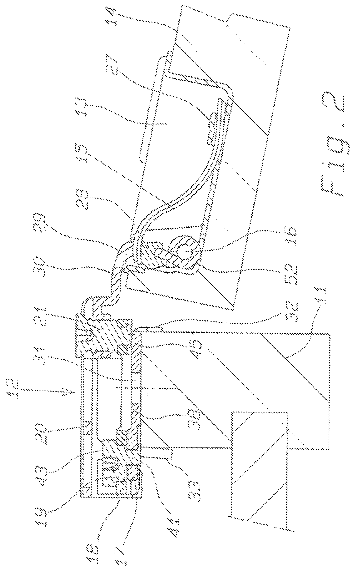
[0026]As more folly illustrated in FIG. 2, the box 13 is connected swingably to the fixed part 12 by an oscillation pin 16 which extends transversally, such that the box 13 can rotate between an open position of the door and a closed position of the door by action of a closing spring 15 of a leaf type housed in the box 13.

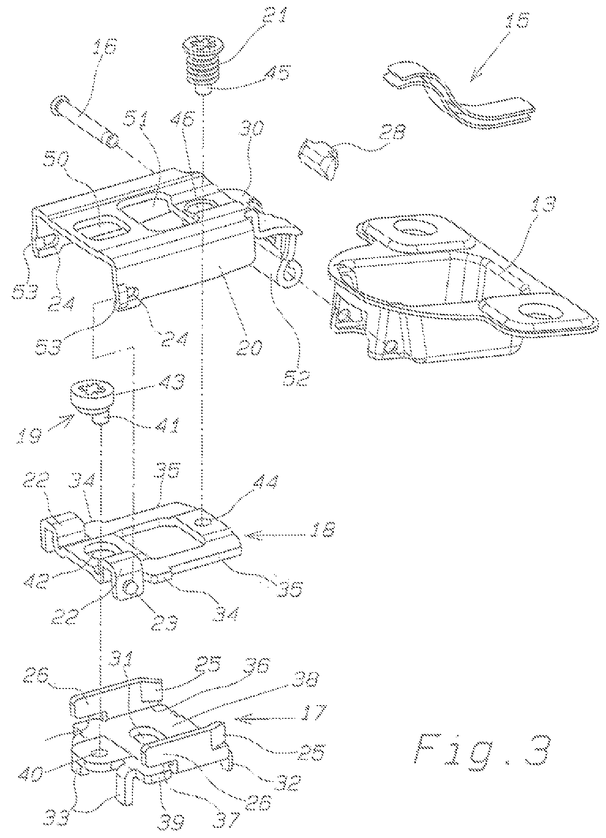
[0027]The closing spring 15 is preferable formed by two identical superposed leaves housed at an end thereof on the bottom of the box 13 for insertion under a bridge 27 formed by cutting of the bottom, as can more clearly be seen in FIG...


PUM


Abstract

The hinge for mounting a door on a piece of furniture provided with a front frame comprises a base plate fixable to the front frame of the piece of furniture, an intermediate plate slidably connected to the base plate and movable by an adjusting cam, a hinge arm connected to the intermediate plate swingably according to a transversal axis and mobile by means of an adjusting screw; the intermediate plate, at a rear end thereof, exhibits side wings having hinging projections which project on opposite sides according to the transversal axis so as to engage rotatably in rear side holes of the hinge arm. The base plate exhibits retaining side parts for the intermediate plate, conformed and arranged such as to retain the side edges of the intermediate plate in a perpendicular direction to the longitudinal extension plane of the base plate.

Description

RELATED APPLICATIONS[0001]This application is a U.S. national phase application of International Application No. PCT / EP2013 / 060453, filed May 22, 2013; which application claims priority to Italy Application No. MI2012 A001121, filed Jun. 26, 2012.FIELD OF USE[0002]The invention concerns a hinge for doors of pieces of furniture provided with a front frame, on which the hinges are fixed.BACKGROUND OF THE INVENTION[0003]In the furnishing sector, with the aim of swingably supporting furniture doors, use is made of hinges comprising a fixed part connectable to the body of the piece of furniture and a mobile part, constituted by a box, connectable to the door.[0004]In the case of pieces of furniture with a front frame for fixing the hinges, typically used for the United States market, the hinges have to have particularly compact shapes and preferably include the box being connected to the fixed part by means of a single articulation pin.[0005]In known constructional embodiments, the fixed...

Claims


Application Information

Patent Timeline
Patent Type & Authority Patents(United States)
IPC IPC(8): E05D7/04E05D5/02
CPCE05D7/0423E05D5/0276E05D7/0407E05D2007/0461E05D2007/0476E05Y2900/20Y10T16/5321Y10T16/53225A47B95/00
Inventor SALICE, LUCIANO
Owner ARTURO SALICE
Why Eureka
Try Eureka